AA implementation on Sonic XL 4K


#1

I’m running the Phrozen Sonic XL 4K (50u xy res). 50u layer prints are sliced with AA set to 8x with processing forced to the CPU. Early tests and observation of the image files shows that the AA is working - at least in the sense that the slice images are smoothed when viewed on screen. The prints have very evident stepping on low angles that suggest the AA isn’t working to smooth the print (in xy - I know we don’t have z)

From an examination of the images it looks like the AA algorithm is just using a gray scale calibrated to the human eye. However such a scale probably doesn’t reflect the sensitivity of the resins.

For example, a pixel that is calculated to be 50% white and 50% black is presumably rendered as 50% grey. However what really needs to happen is that it is rendered a grey shade that results in 50% resin polymerisation, or more accurately a degree of polymerisation leading to a 50% volume of resin polymerised on the model.

I could look at photoshopping the slices or otherwise testing all this but maybe you have a solution?


#2

Interesting thought! We discussed this here some weeks back as well.

In theory yes you are right. The pixel values should be post-converted to be plotted on the logaritmic polymerisation scheme if one was completely correct.

The hard part we think is that any fully illuminated pixels that are neighbours of the AA pixel will influence the AA pixel as well. Some images from Autodesk floating around on the internet where you see the pixels start growing at their neighbours. Why? Probably because there you have distorted light from neighbour + own light from the AA’d pixel?
Probably why a very ‘dark’ pixel that is AA’d is still showing effect is because of these neighbours.
makes sense?

Regarding the Z effect; we think a dittering might make more sense to try and prevent the lines. It’s on the list.

If you are able to try it with photoshop of course; it would be very interesting to see if there is any result!


#3

I guess there are two parts to this sort of discussion:

Does the idea work?

Given the Autodesk video and some experiments using Gaussian blur on slices (by batch Photoshopping slices) published on the Phrozen forum a while ago, I don’t think there is any doubt that image manipulation can generate smoothing in real world prints via grey pixels. The Autodesk video suggests that very fine control is possible, but in fact if one started with 50u resolution and could split that to 10u by grey scaling then that would be more than adequate for most purposes. Even 25u would be a very good start. AA should do this, but experience suggests it isn’t working well in the real world.

Looking at prints from my Sonic the pixel definition is very clear on the print surface in x, y znd z. This would suggest not a lot of xy bleed is happening. Certainly don’t see this with my Solus where optical factors probably produce a more diffuse pixel image at the FEP.

Which leads to the question of implementation. The first thing to consider is the desired outcome. On large organic models a gaussian blur approach is probably ideal, surrendering some absolute resolution for very smooth surfaces is an acceptable outcome. For small, hard edged models with fine detail this would intuitively be less helpful, and a strict interpolation approach would seem better.

I’ll think about how this might be proven to support implementation.


#4

Mm so you are saying the distortion is not a big factor?
We’ve “measured” with anycubic photon machines a while back. But i remember that the items we printed always varied a bit in size. Partially because of Zbleed from the previous layer and partially because of xybleed.

In either case, i just thought of a nice way to handle this. It might make sense to make a ‘generalized’ formula field to apply as a post processing filter.
So you could enter your own relationship. Input and output would be the 0-255 bits value…


#5

I think the acceptability of ‘distortion’ depends on the model/use. A large bust will not be judged on sub mm dimensional accuracy. A small scale model part certainly will.

Looking at my Phrozen prints there is a clear ‘screen door’ effect on surfaces. You can see each pixel clearly. This demarcation between pixels may be part of the reason AA does not work that well - they are simply too discrete for grey pixels to have an effect. Clearly the design of the printer has sought parallel light and minimised the distance between the LCD and the polymerising resin - intuitively good ideas. However, the LCD image is not a perfect render of the underlying model and this approach focusses on the former, possibly at the expense of the latter.

Achieving a bit more xy bleed would go some way towards improving surfaces. This is not theoretical. Some have detuned the light path to introduce diffusion. This has a very significant effect on surface quality, without much impact on definition. Another idea would be to increase the distance between the LCD and the FEP (might help with LCD longevity too).

Which is all a long way of observing that the issue of surface smoothing and AA may be a combination of hardware and software. This has been brought to sharper focus for me by initial experiments with Gaussian blur added to layers. Added blur can smooth xy stepping, but the extent of blur required to achieve meaningful smoothing is really high - far higher than I’m comfortable with for the fine detail parts that I print as detail loss becomes a problem. It also suggests that AA is largely a waste of time (for this technology as currently built) as the relatively subtle smoothing of AA is trivial compared to the high blur needed to get a result. (I will try to post some results when I have photos)

I originally wanted to see a purely software result as the Autodesk data suggested it should be achievable and very useful. I’m now leaning towards the idea that adjustment of hardware to get less discrete pixel images at the FEP may be needed before software enhancement can be very effective on LCD printers.

I’m not entirely sure I get your filter suggestion, but sounds promising in principle. However I think to subtle for things as they stand.


#6

Curious about any images you might obtain.

Filter -> i propose to just make a 1 line flexible formula like the gcode parser.
You enter the computation that should happen to the byte value of a pixel.
Example: outputByte = YourFunction(inputByte, layerthickness, exposuretime, IsBottomlayer)
where YourFunction could be any mathematically formula.


#7

one more thought… the research images from autodesk were most probably made on an Ember machine. These had a 800x1280px DLP chip. So completely different to LCD in terms of pixel borders…


#8

I haven’t had much time to progress this. I am writing it up, but hard to photograph well and still in progress.

So far I have done some greyscale calibration to look at grey values v extent of polymerisation in Z. Z was chosen as it is far easier to work with than x/y.

Grey values manipulated in Photoshop using %B values (where 0%B is black and 100%B is white - something of an approximation as they will be mapped onto 256 point greyscale, but good enough)

Obviously somewhat resin specfic and will depend on the exposure settings.

In my test model it was relatively easy to visually assess the endpoint greys that coincided with full (over 88% B - 224,224,224) and nil (less than 52% B - 133,133,133) effective polymerisation of the layers. Visually, there was a smooth increase in layer thickness over this range, but I do not have the means to measure this.

The key take home, therefore, is that the grey scale range currently used for AA is very different to the range that covers nil to full polymeriation.

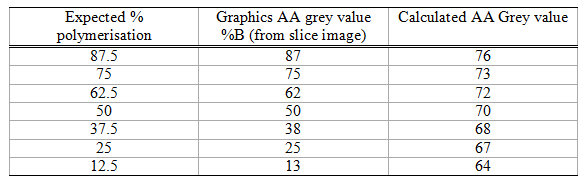
If we assume that within the effective range the extent of polymerisation (= layer thickness) is sigmoidal then then we can map the grey level calculated by the AA algorithm to a grey level that should give the required exposure to the resin. Something like the table attached, where the calculated value gives the expected polymerisation. 50% polymerisation being 25u for a 50u layer.

Thoughts so far:

  • As expected resin behaves differently to the human eye and AA intended for visual graphics produces slice files that are not ideal for smoothing print surfaces.

  • Current AA uses an 8 level grey scale. Assuming sub pixel resolution is achievable, this would produce a theoretical 6u resolution for 50u pixels. This is probably more than needed. Even 25u would be a significant improvement in surface smoothness, and 12u would be extremely good for most purposes.

  • Chasing xy AA too far without addressing z axis AA is probably wasted effort.

  • I need to print some tests with no AA, AA as currently implemented and a manually adjusted AA according to the attached tabe to compare actual surface smoothness in the printed model for xy.

image