I am not sure if this is a bug or I am just doing something stupid.
Using Formware 3D version 1.0.2.4 when I add drainage holes they stay as solid plugs instead of creating holes in the part.
Thanks for any help,
Tony.

I am not sure if this is a bug or I am just doing something stupid.
Using Formware 3D version 1.0.2.4 when I add drainage holes they stay as solid plugs instead of creating holes in the part.
Thanks for any help,
Tony.
Hi Tony,
yes this is not a bug.
They are boolean differenced when you are slicing. (SVG/SLC/PNG/GCODE)
Reason being that a full 3d mesh boolean difference is very hard to do right.
2D it ‘always’ works.
I’m currently writing a 3d full mesh boolean for the holes.
Mainly because this question is asked now 20+ times 
And with the current setup one can’t export the entire structure as STL with holes…
So this will be in the next update.
Elco
Not sure if Formware checks normal orientation or autofixes, but perhaps your normals are reversed?
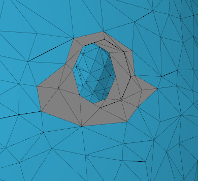
Yes no worries. It’s just an image from my debugging console… the gray triangles are to be placed in the general mesh. (they are gray so i see what i’m doing  )
)
Hi Elco,
Thanks for that info.
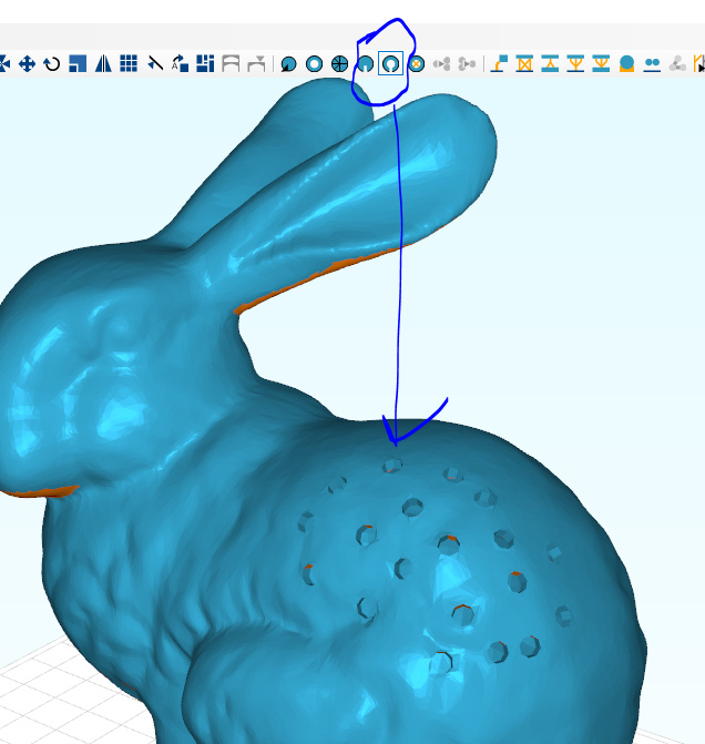
Just to be clear though I am not exporting the part to STL, just slicing it normally. In the slices the drainage holes are solid so no holes appear.
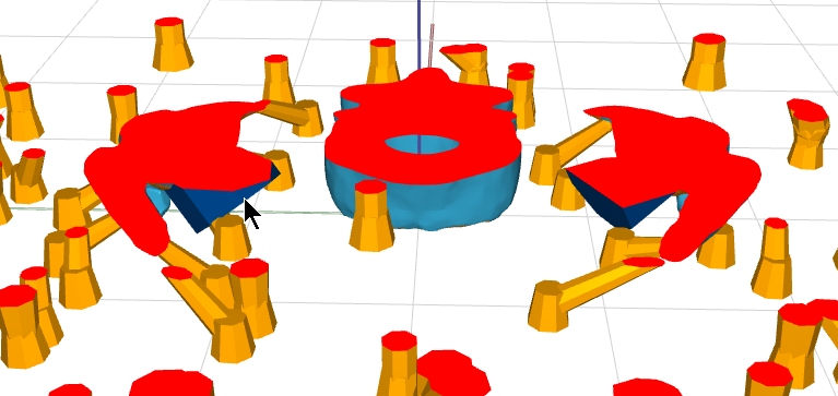
In the image the cursor points to one of the drainage ‘holes’. It did not cut through the part but remained as a solid. The part is light blue and the drainage holes are dark blue.
Hi Tony,
Yes that’s correct behaviour.
Once you start slicing it will revert the meshes and create the actual holes.
You see the hole in the PNG’s.
I’ve finished the boolean implementation yesterday; need to wrap it up and polish it.
So a ‘real’ hole will be possible in couple of days from the software.
kind regards,
Elco
Hi Elco,
Excellent support as always. I didn’t think to look at the actual slices in the cws file. Yes, the holes are there. Now I understand.
Thanks,
Tony.
I’ve uploaded a new version of the installer that includes the complete boolean.
It works better than I expected but still took around 2 days to code. Still far from perfect and you can see i smuggle a bit with the triangulation of the planes near the holes. But I figures; a drain hole is by definition on a side where you don’t want it to be seen in your model.
A word of caution; if you do this with very big meshes it will take a memory load because of the ‘undo/redo’ functionality storing modified meshes.
Many thanks for that.
I downloaded and installed the latest but it still shows 1.0.2.4 in the about box and the drain plugs are still there.
I didn’t see it. Sorry.
I am glad you left the other button because the new format requires a lot faster computer.
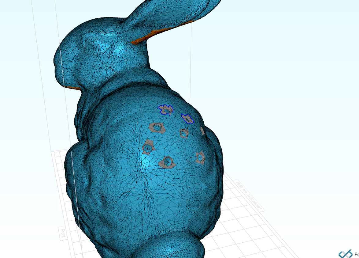
I tried a few models. Generally the holes work well but in some cases around the hole is a thin wall coming up from the surface. After the hole process is finished there is an error in the part shown as the warning sign beside the STL part name.
It appears that if i place a hole where there is geometry just behind the wall this is where the errors occur.
It just requires a bit more care in placing the holes. Then they work well with no errors in the STL file.
Thanks for the feedback.
In the end the mesh boolean is one of the hardest things to do mathematically.
If the mesh is not 100% watertight it will yield errors very fast.
Even if for example, you have a clean mesh be it with multiple disjoint shells.
(which prints fine) you can still get holes that are problematic…
I’ve tried to set it up as forgiving as possible.
It will show an error message when it didn’t manage to find 2 closed curves where your hole crosses the mesh.
However still then there are many things that could go wrong…