Function "part replace" shifts the new part to the side


#1

Hello
During printing I noticed some problems on the file, so I changed the part in CAD and replaced the old part with the new obj file. Strangely the replace function shifts the part to the side, so it does not fit original position. The basic file did not change position. So the parts origin is exactly the same.
Any way to get it back to its original position? Very strange. I remember that this always worked.
Moving it back manually is nearly impossible. I´m using latest Formware version.
Thanks for your help.

Best regards, Chris


#2

Hello
Anyone has any idea to this?

Best regards, Chris


#3

Hi Chris,

I’ll check that thanks. (somehow your post missed my attention).
Can you check in the settings what it does on import of a part? (config -> import options -> first dropdown)
It seems like it auto-centers is. Perhaps the ‘replace’ toggle is not applied correctly somehow.
Perhaps you put that to ‘none’ it will not center it and just import in the default coordinates (what you want).

kind regards
Elco


#4

Hi Elco
Thanks for your quick answer.
No, even with deactivating the auto-placement it does not fit the “old” place.

But even with deleting the copy, and centering the part, it shifts the position:

Thanks, Best regards, Chris


#5

Hi Chris,

I’m looking at it but can’t find the cause yet.
Is this the only part this happens with?

There are some operations that recalculate a mesh, and set the transformation matrix to identity (1).
For example shrinkwrap or hollowing, it recalculates coordinates and removes transformation.
(while writing this not sure this is actually prefered behaviour)
So did you do any mesh type operation on this part?

kind regards
Elco


#6

Hi Elco
I usually do the mesh repair before. But that is the only mesh operation I do.
I had this on some parts, but cannot remember which were affected and which not.
Interesting is the fact, that replacing it by exact the original file - the shift happens as well.

Best regards, Chris


#7

Hi Chris,

I don’t think mesh repair replaces the coordinates.

But if it does happen with the original; then could if be they have different coordinates?

You can verify this by setting the import transform to ‘none’ (like before)
Then import both meshes. If they have the same coordaintes, they should be on top of each other.

Elco


#8

Hello

I now found out it is definately caused by Mesh-repair. Before doing mesh repair, you can replace it as often as wanted with no effect to position. After doing Mesh-repair, the part is replaced to an other position. It seems the “base-coordinates” are reset - or something like this …
I can definately reproduce this happening with all parts I have.

Best regards, Chris


#9

Hi Chris,

Thanks for sorting this out.

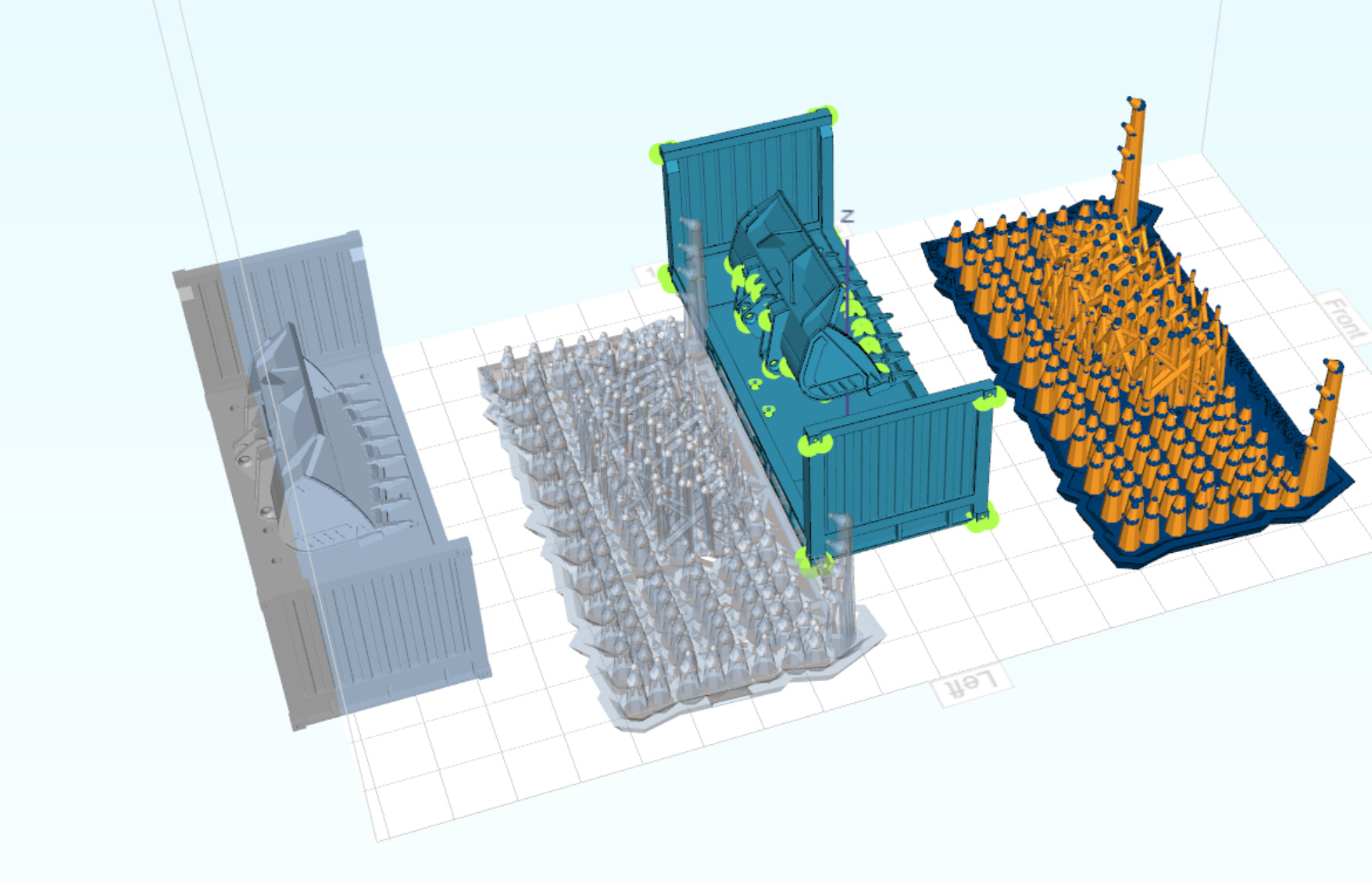
Just to give some context on how 3d software works, i didn’t give earlier, but i think will clarify what happens.
Each mesh has it’s ‘local’ coordinates. These are usually equal to what is in the STL file.

Then there is usually 1 matrix which is called the transformation matrix; that transforms the local coordinates in world space. This matrix is just kept in memory in the software. So world space is the axis system of your printer… XYZ.
Whenever your part is drawn on the screen; the GPU multiplies the local vertex coordinates with the transformation matrix to get the world coordinates. (and some more but that’s not relevant here).

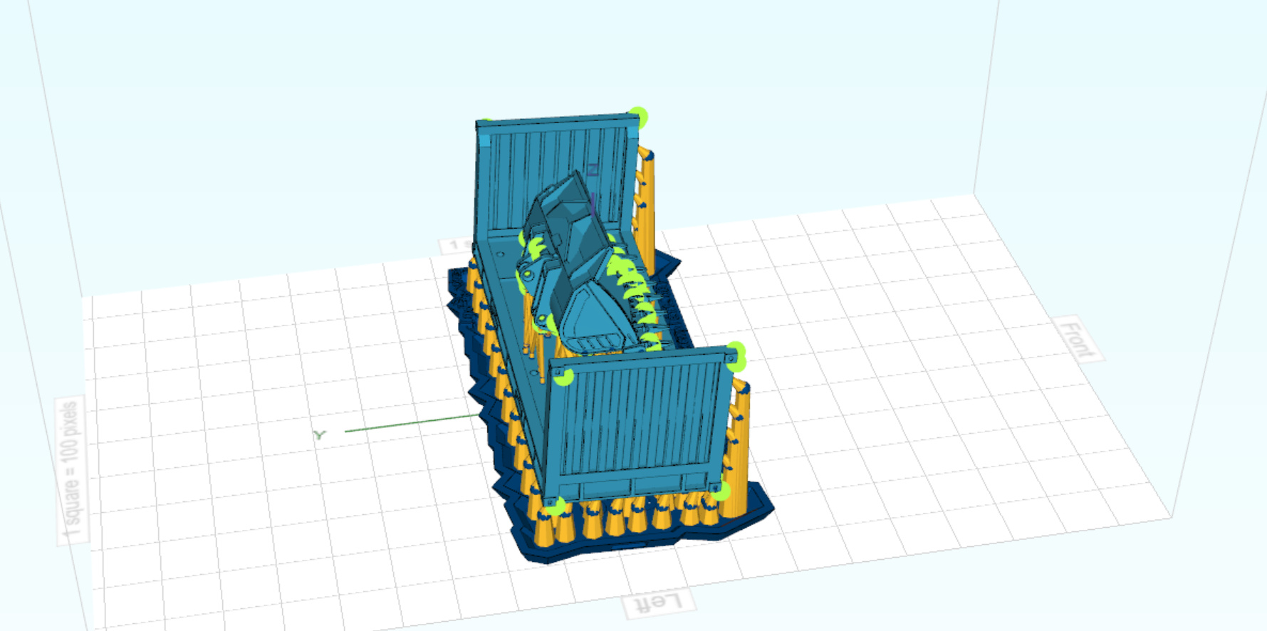
So if you ‘drag’ the object along the x axis; that transformation will go into the transformation matrix with just 1 digit; and the mesh vertices will all remain the same local vertices, loaded from the file.
(you can’t recalculate vertices every time you do an operation… it’s to slow)

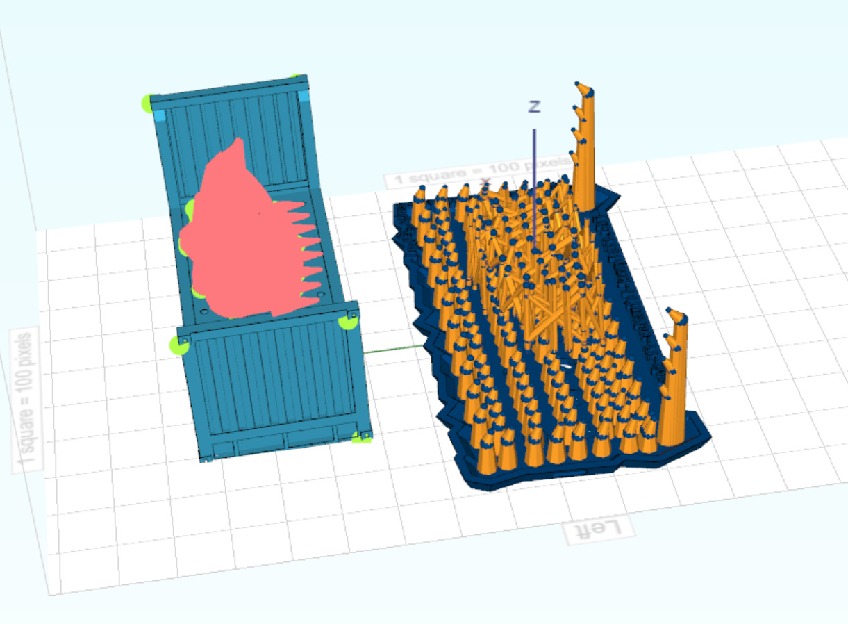
Now; I just checked my code there; if you pull of a repair operation; what will happen is that before the repair it will perform the calculation of world vertices (same that happens on the GPU).
I don’t know why I did this; probably the idea was if you have multiple disjoint parts in the mesh they could have different transformation matrices; but that never got developed.

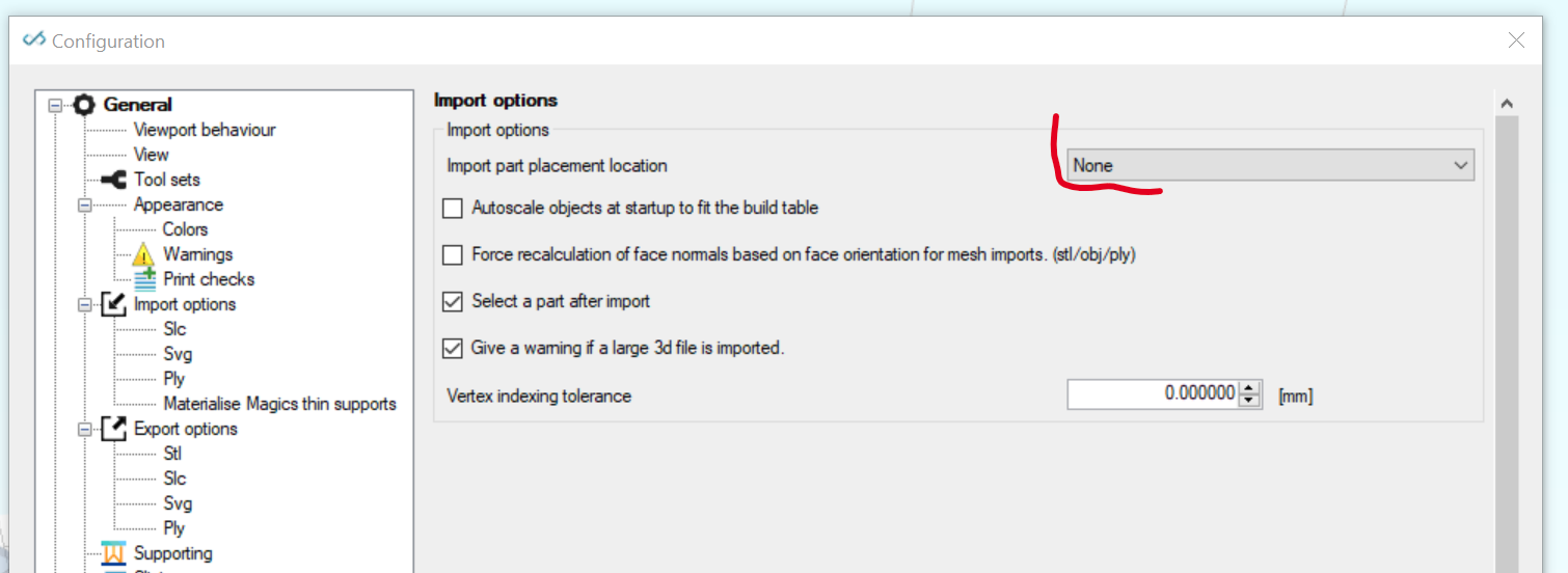
So i will modify this in the next release that the repair keeps local coordinates… then the problem should be solved. The local coordaintes will remain; transformation matrix unchanged; then the re-imported part should stick to the same location.

kind regards
Elco


#10

Hi Elco
Thanks for explanantion and solving of the problem :wink:

Best regards, Chris


#11

Hi Elco
Has this problem already been solved? Or differently asked - is the release with that fix
already online? I still have this problem …

Best regards, Chris


#12

Hi Chris,

Yes this is fixed in our development version.
I have not released a new version for a while; as i’m working on some bigger updates; most notably our nesting engine is redone compeltely which took some weeks.

If you wish I can make a build for you and send you a wetransfer.

Elco


#13

Hi Elco
Thanks for the quick answer.
Yes, this “wetransfer” - build would be great. Then maybe I can contiunue working on some projects.

Thanks, Best regards, Chris


#14

The transfer is uploading. V1158 beta. I’ve used the email from your forum profile.

For the nesting parts; only the rotations are not completely done. But it works. Just make sure to leave the custom rotations empty if you don’t want to use those.

Elco


#15

Got it …

Thanks Elco - Great Service


#16

I don’t think mesh repair replaces the coordinates.