Gcode not being written correctly


#1

I have extracted the run.gcode from a sliced .ctb file, and it is not being written with the correct values. The extracted header and first layer are:

;fileName:
;machineType:default
;estimatedPrintTime:1692
;volume:0
;resin:default
;weight:0
;price:0
;layerHeight:0.04
;resolutionX:3840
;resolutionY:2400
;machineX:199.68
;machineY:124.8
;machineZ:1.36
;projectType:mirror_LCD
;normalExposureTime:3.1
;bottomLayExposureTime:3.1
;bottomLayerExposureTime:3.1
;normalDropSpeed:450
;normalLayerLiftHeight:20
;zSlowUpDistance:6
;normalLayerLiftSpeed:30
;bottomLayCount:5
;bottomLayerCount:5
;mirror:1
;totalLayer:35
;bottomLayerLiftHeight:20
;bottomLayerLiftSpeed:30
;bottomLightOffTime:1
;lightOffTime:1
;START_GCODE_BEGIN
G21;
G90;
M106 S0;
G28 Z0;

;START_GCODE_END

;LAYER_START:0
;currPos:0.00
M6054 “1.png”;show Image
G0 Z20.00 F30;
G0 Z0.00 F450;
G4 P3100;
M106 S255;light on
G4 P1000;
M106 S0; light off

;LAYER_END

However, it should be:

;fileName:ResinXP2-ValidationMatrix_200701.stl
;machineType:Phrozen Sonic Mighty 4K
;estimatedPrintTime:1601
;volume:1.651
;resin:Siraya Fast - 40 Micron
;weight:1.6514
;price:0.0826
;layerHeight:0.04
;resolutionX:3840
;resolutionY:2400
;machineX:199.68
;machineY:124.8
;machineZ:1.4
;projectType:mirror_LCD
;normalExposureTime:3.1
;bottomLayExposureTime:3.1
;bottomLayerExposureTime:3.1
;normalDropSpeed:450
;normalLayerLiftHeight:20
;zSlowUpDistance:5
;normalLayerLiftSpeed:42
;bottomLayCount:5
;bottomLayerCount:5
;mirror:1
;totalLayer:35
;bottomLayerLiftHeight:20
;bottomLayerLiftSpeed:42
;bottomLightOffTime:25.5333333333333
;lightOffTime:25.5333333333333
;START_GCODE_BEGIN
G21;
G90;
M106 S0;
G28 Z0;

;START_GCODE_END

;LAYER_START:0
;currPos:0.04
M6054 “1.png”;show Image;
G0 Z20.04 F42;
G0 Z0.04 F450;
G4 P3100;
M106 S255;light on
G4 P25533.3333333333
M106 S0; light off

;LAYER_END

The job start gcode is:

;fileName:$FirstPartName
;machineType:Phrozen Sonic Mighty 4K
;estimatedPrintTime:$PrintTimeEstimate
;volume:$VolumeMl
;resin:$ProfileName
;weight:$Weight
;price:$Price
;layerHeight:$LayerThickness
;resolutionX:3840
;resolutionY:2400
;machineX:199.68
;machineY:124.8
;machineZ:($SliceCount * $LayerThickness)
;projectType:mirror_LCD
;normalExposureTime:$ExpTimeSeconds
;bottomLayExposureTime:$ExpTimeBottomSeconds
;bottomLayerExposureTime:$ExpTimeBottomSeconds
;normalDropSpeed:$ZRetractSpeed
;normalLayerLiftHeight:$ZLiftDistance
;zSlowUpDistance:5
;normalLayerLiftSpeed:($ZLiftSpeed * 1.4)
;bottomLayCount:$BtmLyrs
;bottomLayerCount:$BtmLyrs
;mirror:1
;totalLayer:$SliceCount
;bottomLayerLiftHeight:$ZLiftDistance
;bottomLayerLiftSpeed:($ZBottomSpeed * 1.4)
;bottomLightOffTime:(((60/$ZBottomSpeed)*5) + ((60/$ZRetractSpeed)*($ZLiftDistance - 5)) + ((60/($ZRetractSpeed*0.5))*($ZLiftDistance - 3)) + ((60/$ZBottomSpeed)*3) + 3)
;lightOffTime:(((60/$ZLiftSpeed)*5) + ((60/$ZRetractSpeed)*($ZLiftDistance - 5)) + ((60/($ZRetractSpeed*0.5))*($ZLiftDistance - 3)) + ((60/$ZLiftSpeed)*3) + 3)
;START_GCODE_BEGIN
G21;
G90;
M106 S0;
G28 Z0;

;START_GCODE_END

The layer gcode is:

;LAYER_START:$SliceNr
;currPos:(($SliceNr+1) * $LayerThickness)
M6054 “($SliceNr+1).png”;show Image;
G0 Z($ZLiftDistance + (($SliceNr+1) * $LayerThickness)) F($SliceNr < $BtmLyrs?($ZBottomSpeed *1.4):($ZLiftSpeed * 1.4));
G0 Z(($SliceNr+1) * $LayerThickness) F$ZRetractSpeed
G4 P($SliceNr < $BtmLyrs?$ExTimeBottom:$ExTime);
M106 S255;light on
G4 P($SliceNr < $BtmLyrs?(((60/$ZBottomSpeed)*5) + ((60/$ZRetractSpeed)*($ZLiftDistance - 5)) + ((60/($ZRetractSpeed*0.5))*($ZLiftDistance - 3)) + ((60/$ZBottomSpeed)*3) + 3)*1000:(((60/$ZLiftSpeed)*5) + ((60/$ZRetractSpeed)*($ZLiftDistance - 5)) + ((60/($ZRetractSpeed*0.5))*($ZLiftDistance - 3)) + ((60/$ZLiftSpeed)*3) + 3)*1000)

M106 S0; light off

;LAYER_END

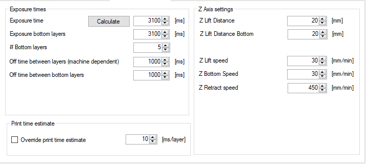
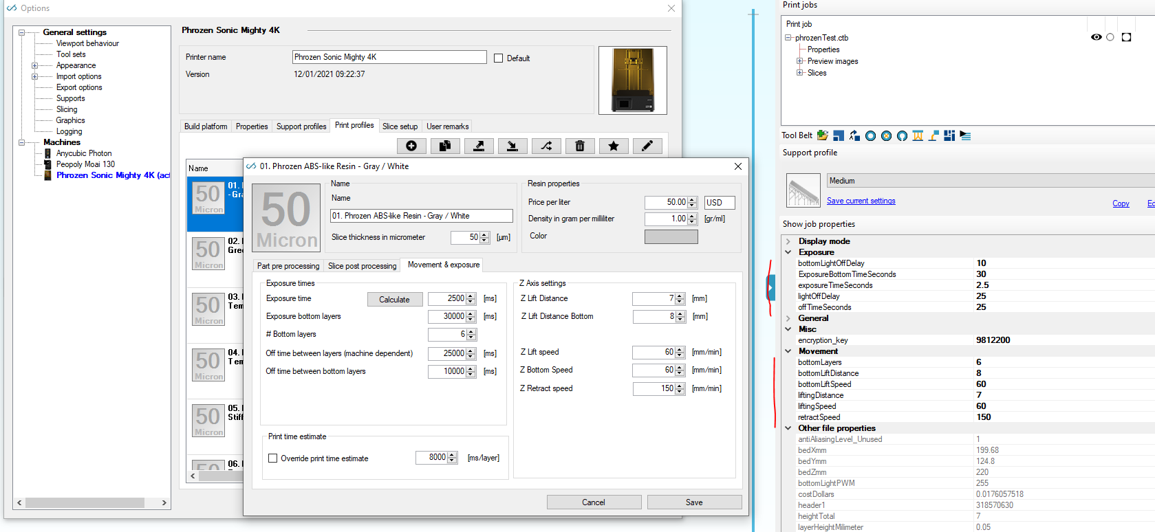
The profile movement section is:


#2

Ok I understand what you are trying to accomplish. The GCode editor is deactivated by default for a reason for these machine profiles (if you add them), that is that these .ctb file format’s don’t use GCode. GCode’s are machine commands to move axis. They are not commands to generate correct header values in another file format (.ctb)

A scripting control over what is outputted to the ctb headers is another function
Might make sense to check if we can use the same script editor for this.

But are you sure that you can’t set the values manually? Because I see no logic other than ‘static’ logic in the formula’s you use? i.e. bottomLightOffTime in the sample you give, it’s only dependent on fixed values that dont’ change correct?

Another question, are you aware that you can edit the CTB file (headers) in Formware as well?
You can load the .ctb file. Then click the properties and all ‘bold’ items are editable.
Then select the print job and go to the ‘export print job’ command to save as .ctb again.
(my apologies for the naming conventions of the variables… we have 10+ formats and it needs a cleanup of these variable names)

kind regards
Elco


#3

The formulae are not static - they take values set in resin profiles and the result of each formula will change with any changes on the movement and exposure tab for a resin profile.

I’m currently putting together a hacky workaround where I’ve enabled the workflow tab, and instead of slicing to a ctb, I’ll slice to a zip file, then automatically run uv3dp to convert the zip file to a ctb, that way the values in the gcode header in the zip file will be used in the ctb.

A quick question though - If I set the print job folder name to XP2, I’ll then get a zip file called “XP2.zip” when the resultant folder is zipped up. I know this will be passed as an argument automatically to uv3dp via the workflow, but I also need to use the print job folder name (And it’s full path) in the uv3dp output file (eg. “c:/path/to/XP2.ctb”), and so I need to know if there’s a variable I can use in the arguments box of the workflow tab that will resolve back to the output folder name with its full path?


#4

Yes i see. You have a dependency machine -> print profile.

But then again; can you point out to me which of these variables are not correctly outputted?


#5

The ones that are used in the calculations in the gcode header. The calculated values are not written to the ctb.


#6

Also, this is a bit of a problem…

I don’t want to have to locate a binary from another source under the Formware installation path, just to be able to use it in the workflow:

22%20PM


#7

So you mean these 3 items?

;bottomLayerLiftSpeed:($ZBottomSpeed * 1.4)
;bottomLightOffTime:(((60/$ZBottomSpeed)5) + ((60/$ZRetractSpeed)($ZLiftDistance - 5)) + ((60/($ZRetractSpeed0.5))($ZLiftDistance - 3)) + ((60/$ZBottomSpeed)3) + 3)
;lightOffTime:(((60/$ZLiftSpeed)5) + ((60/$ZRetractSpeed)($ZLiftDistance - 5)) + ((60/($ZRetractSpeed
0.5))*($ZLiftDistance - 3)) + ((60/$ZLiftSpeed)*3) + 3)

A quick fix would be just calculate them and insert their boxes.
Long term: i think it’s good for us to check if we can make everything more flexible with variables. Like i.e in Fusion360.

regarding the path, please use backslash… like C:\uv.exe


#8

There’s another problem

I have this set:

39%20PM

But $ExpTimeSeconds is 3. Not 3.1 as it should be.

It gets worse. ($ExTime / 1000) is also 3, not 3.1


#9

In the latest version for the GCode export i’ve set the ‘second’ outputs to 3 decimals.

So
$ExpTimeSeconds
$ExpTimeBottomSeconds
$OffTimeBetweenLayersSeconds
will get 3 decimals.

$ExTime
$ExTimeBottom
$OffTimeBetweenLayers
will get 0 decimals. (as they are in milliseconds)

Just to be clear for other readers. If you just use the normal CTB export there are no issues with this. It exports 3.1s as one would expect.

Elco


#10

Thanks Elco. Yup, can confirm the export to CTB used the correct figures previously, it was just the gcode that didn’t.

I’ve taken your advice and plugged in the calculated values into the resin profile, I can confirm it appears to be working. I won’t need to recalculate for exposure, only if I change the speeds and heights.