
I’m thinking about using Formware for my Moai 130 but I don’t see any documentation about how the “SLA Coordinate correction” works. Does anyone have screen captures of the interface or specific instructions on how to set it up? Any examples of the “lineair correction mask” that’s mentioned in the documentation? Thanks
SLA Coordinate correction for Moai 130
formware
#2
Hi Jonas,
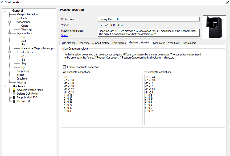
It’s basically a lineair interpolation correction.
It’s some time ago but if I remember correctly the values came from the Moai example in Cura back then.
They used another (strange) definiton of the values.
We switched that to absolute correction.
So the first value is the X or Y value, the second value is the correction in mm.
You can just take a simple cube to see what it does. Export the gcode print job and re-import the .gcode file.
It will overlay the gcode lines.
Put a cube in every corner of the build plate to view the correction.
Elco
JonasGrumby
#3
That’s great. Thanks for the info. That is basically the same way that Asura handles the corrections. Plus and minus on the X and Y every 10mm.
Aquilux
#4
Hey, I actually just posted this on the peopoly forums but you had said you were more active here:
I noticed there was some question as to the mechanism behind why more correction was needed as you moved away from center, and I think understanding why might help overall.
I believe the largest error comes from what is referred to as cosine error, because the gcode x/y commands actually represent laser angles rather than bed positions. On top of that there are probably electrical impedance issues as you pump larger voltages through the magnet coils used to move the mirrors, but that’s probably a smaller problem than the cosine losses.
In fact there’s an entry on the “instructables” site where someone tangles with exactly this problem. Peopoly probably decided to do this correction on the computer running the slicer rather than on their control board.
Another thing to look into is related to the little circles you do for the sharp corners. Interestingly this is actually done on CNC milling machines because of the momentum in the large moving metal parts involved. On this printer and others like it, the momentum of the galvo assembly and the electrical “lag” caused by the coils acts much like the physical momentum I mentioned. There’s a picture on the other post of the path demonstrated in fusion 360 when building gcode for cutting (the loop is in green, default colors, sorry)
It might also be useful to mimic other behaviors as well. For instance, all cutting moves have a “lead in” curve, partially to accommodate cutter geometry, but it also gives the tool head time to change directions before committing to a cut.
formware
#5
Hi Aquilux,
Thx for this info!
Yes we’re aware of the cosine error and the reason for this correction.
I think peopoly did it in this way probably because formlabs before them also had this kind of correction grid if i remember correctly. (Not sure which one started first actually)
The inertia of the tool/galvo is indeed what is stopping you from doing a sharp corner. I think there is no such option in Cura because cura is FDM by default; and you don’t want to have the plastic dragging along. So they have to do a sharp corner. I spoke to a laser company some days ago and they mentioned that this technique is actually already older, it’s also used in laser marking and there it’s called ‘sky writing’…
I know fusion360 of course. The lead in move goes most often in the Z direction if i’m not mistaken. And that direction is not really there in an SLA machine…
kind regards
Elco
Aquilux
#6
True, the lead in’s major component is in Z as the primary consideration in that situation is reducing cutter contact and risk. That being said, there is an x/y component that fusion 360 (and I imagine other CNC software) uses explicitly for sharp corners to better manage the inertia of the machine in those axes that is similar to what is being dealt with in our case, and I was proposing the possibility that looking over how those challenges were solved there may give some useful insight. Though you may have already explored that and found everything of use already.
As for the the cosign error, my apologies if I just rehashed things you already knew, I was going off the comments on the peopoly forum mentioning that you didn’t understand why they did what they did. I must have misinterpreted what aspect you were perplexed about.
formware
#7
What I ment with this is that is interpolates lineair into the correction values. So if you enter correction values that assume a cosine correction (which i believe is done in assura, or with the default values) you get a cosine correction. So you are free to choose whatever correction you apply. If I remember correctly the Moai had a procedure of finding the correction map.
Elco