Support Generation - Unintended Behavior


#1

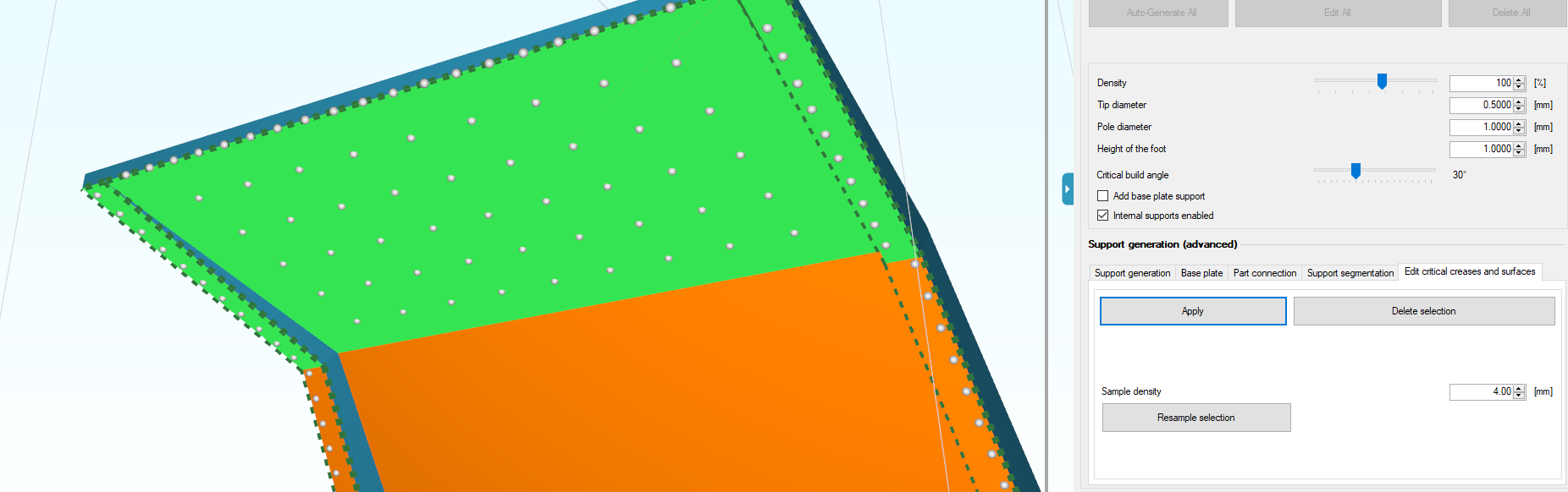
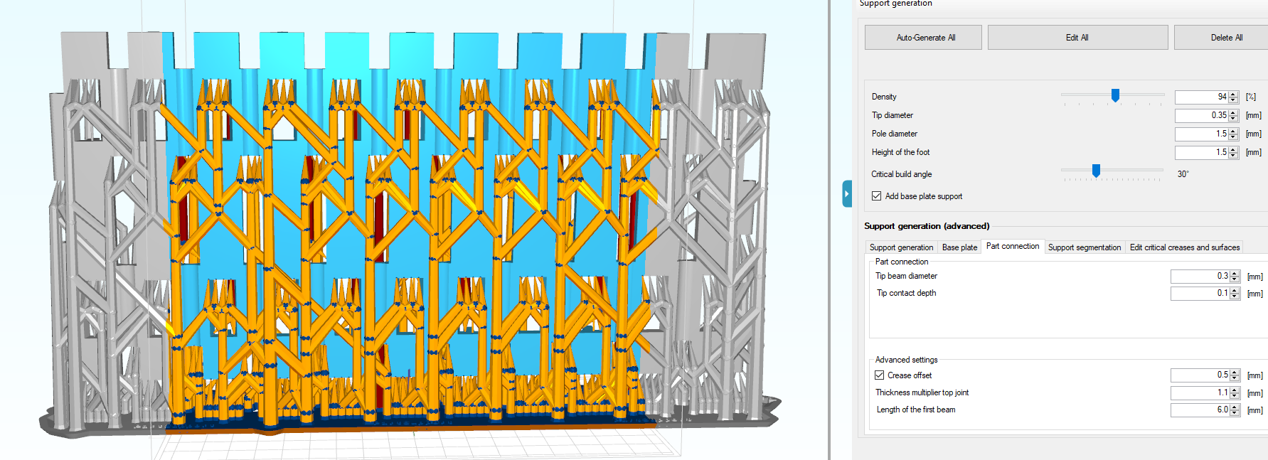
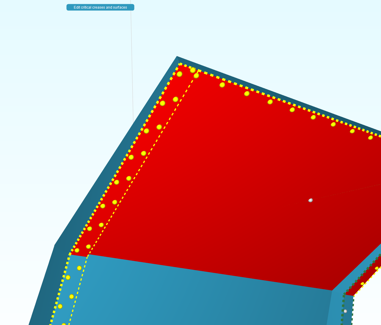
One feature I truly enjoy using is the “Edit critical creases and surfaces” function. It works 98% of the time I use it. It makes quick work of fine tuning supports based on the differentiation of critical surfaces.

But I have noticed a few issues. The main issue being that an applied change to sampling density doesn’t always translate into the supports appearing like you would expect.

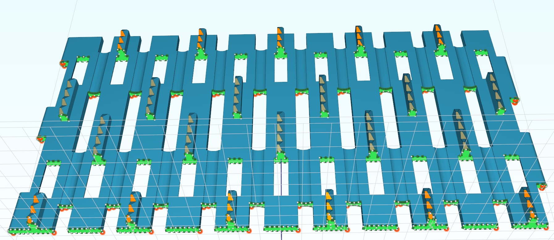
Adjusted sampling preview result:
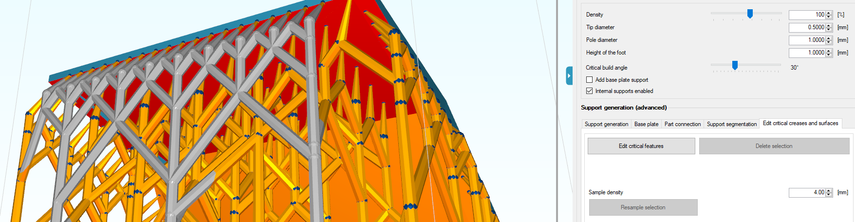
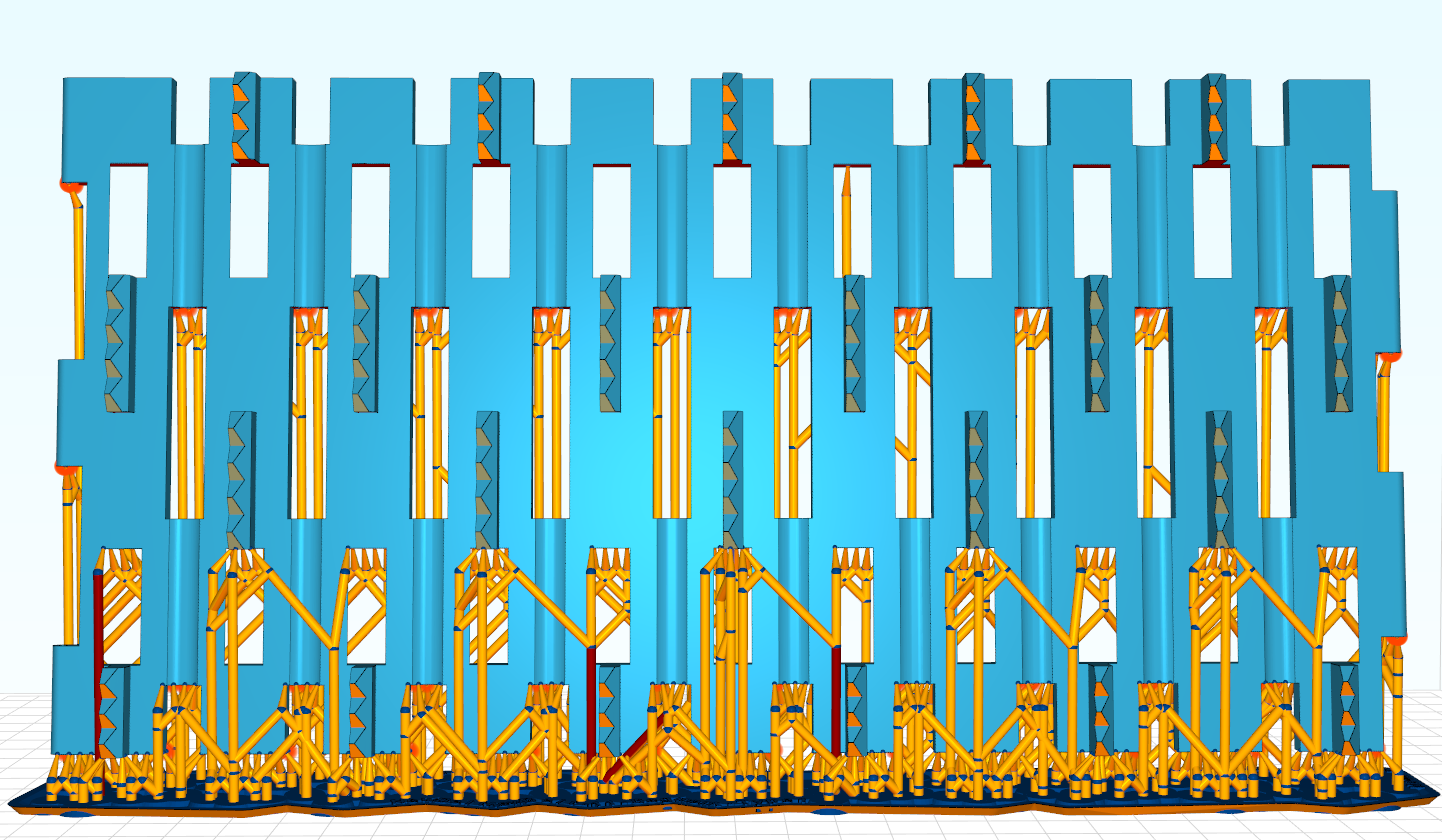
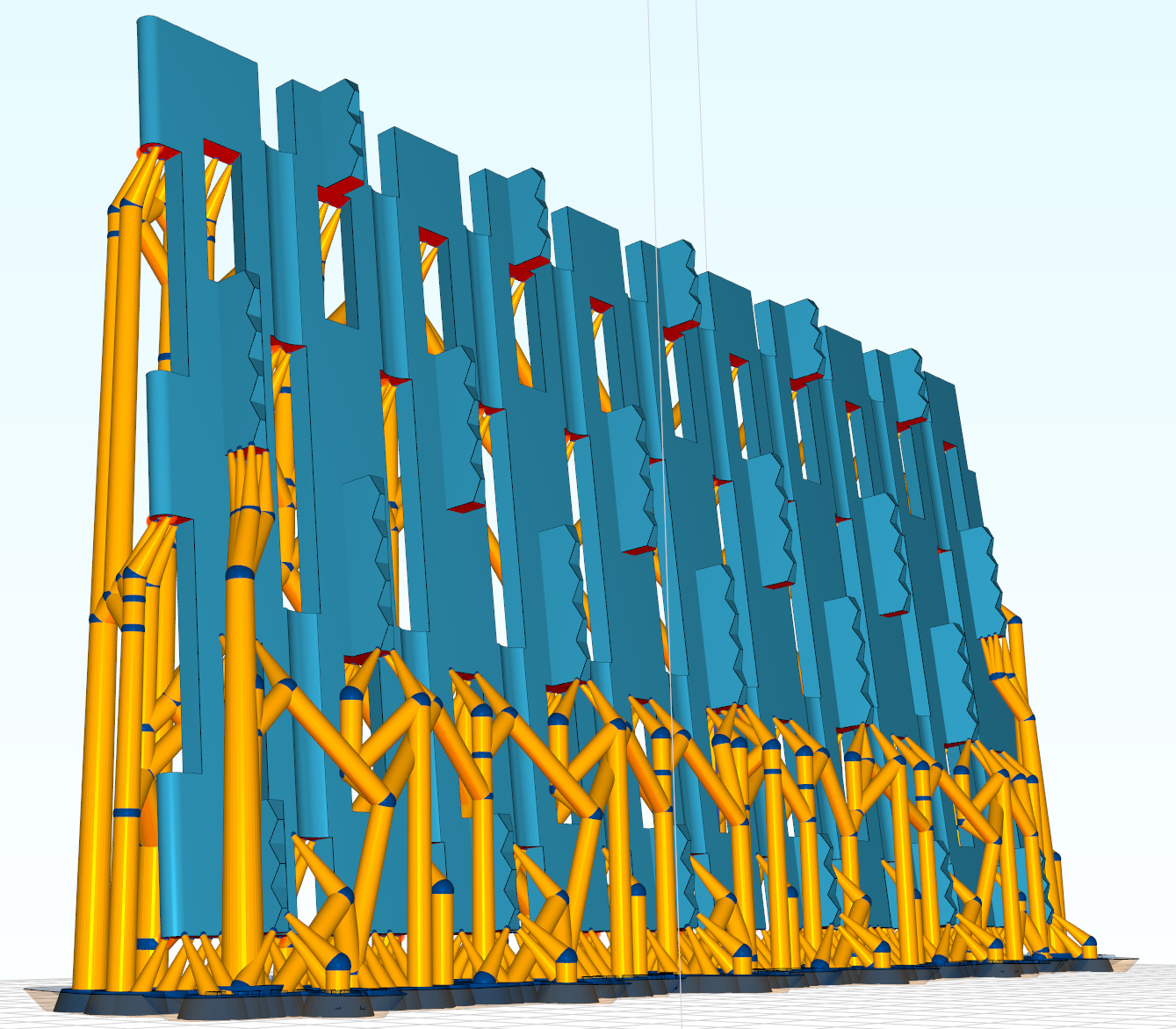
After applying:

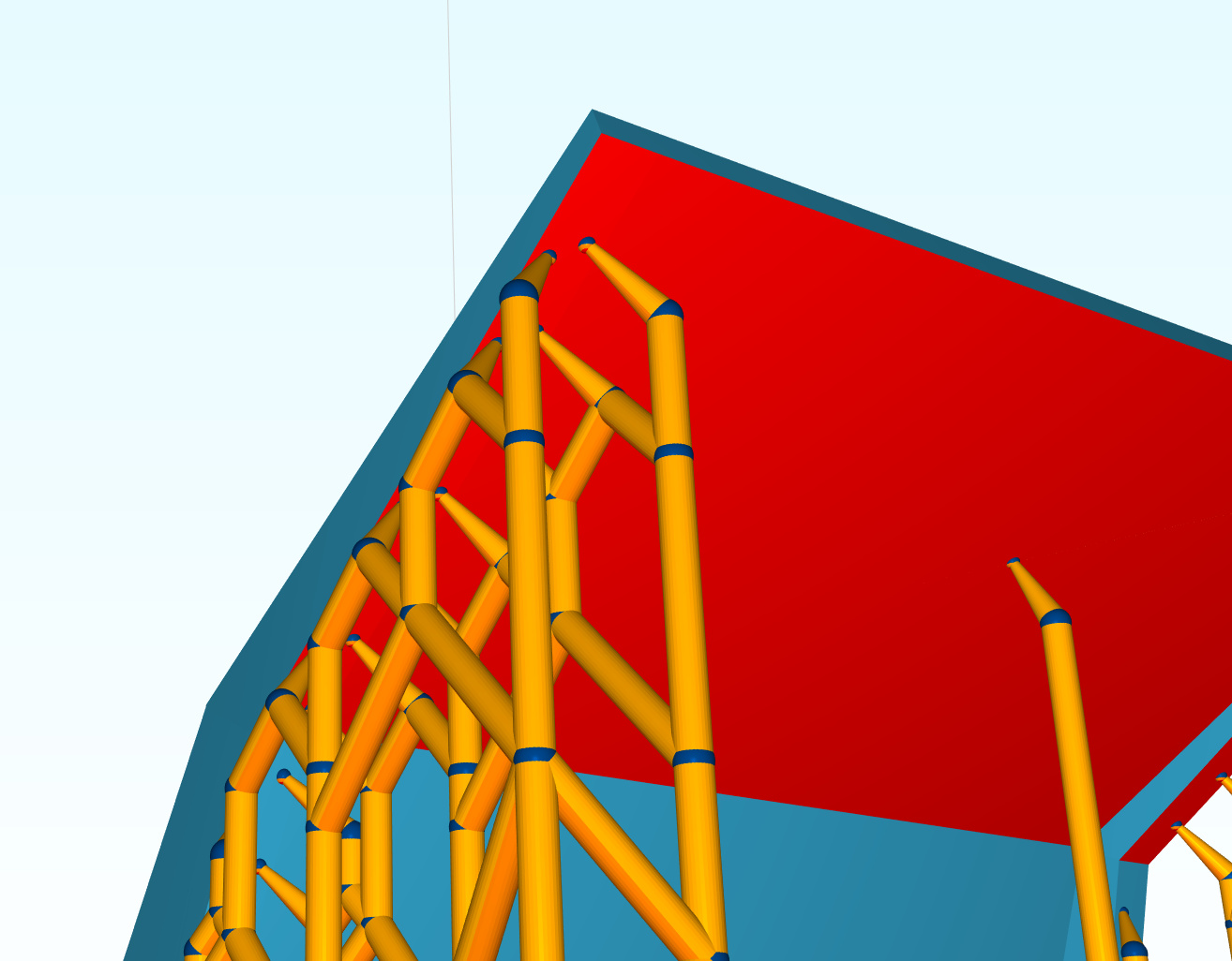
What might be the reason for the predicted/expected support points not resulting in the creation of a support(s)? I’ve checked my model for flaws and tested many different support parameters. Nothing is below my model which might interfere with the support calculation or placement. I’ve ran into this phenomenon with a few models of mine. Might I be doing something wrong? Or is there a way to force those points to be used for support generation?

When placing single supports for the area not covered due to the above issue, can a lattice structure be constructed between single supports? The “Add a connecting bar between existing supports” function is broken for me. The program will just hang (version 1.0.3.7). I’ve tested and it doesn’t matter how tall or fall apart the selected supports are from one another. Might there be another way to join supports?

Let me know if you need any files.


#2

Hi,

Yes please email us the file that gives this trouble. I can’t tell exactly why it behaves like this but it shouldn’t when i look at the image :wink:

The moment you generate supports it always filters the points to prevent any extreme densities.
There are additional filters that check for to many points along boundaries of critical surfaces. Could be something is off there.

Regarding the connection bar; strange. I’ve just retested to be sure but seems to work here. No other reports so far of this. Is it also in the same file?

Elco


#3

Tail Section Final.stl (1.8 MB)

Thank you for the quick response. I’ve attached the STL file. The orientation of the object in the file is how I intend to print the part. I played with the spacing/sampling value (2-6 mm) and couldn’t get supports to form on the uppermost cross-section (as shown in the images).

I have issues with the connection bar feature on other models. Tested it on a few other object and the same behavior was noticed. The program would lockup and be unresponsive after selected the second support. I’m attempting to connect two manually placed single supports. It only fails if one or both supports are manually placed. The function works perfecting if I select two supports which were created with the automated function.

Let me know if you can reproduce this issue. Might there be a debug or logging state which can help pinpoint the cause of the issue? Don’t know if this is a problem specific to my installation.


#4

Hi,

I’ve finally had some time to have a look at this file; but no solution or problem found yet. There might of course be a bug but I can’t reproduce it at the moment without exact steps.

When I load it and run the supporter it looks like this.
Then when I edit some creases and increase the density it results:

Then the placed supports:

points to note:

  1. I slightly rotated the model to have the side flanges also critical surfaces (this shows from your image but when I load the stl without rotation these flanges were not critical

  2. the algoritm for crease detection walks up from the bottom to whatever crease it’s connected to. So some of the creases contani multiple branches. They might not be evenly distributed in a model like this. That should not matter as long as you sampling density is similar… probably what one would want.

  3. the algoritm first samples creases. Then surfaces; but removes any points that are closed to an already sampled crease. That is to prevent oversupporting.
    I’m thinking maybe there might perhaps be a memory bug somewhere, as it would save previous points somehow and prevent newly sampled points to show up. But I can’t put a finger on it yet…

Elco


#5

Thank you for thoroughly evaluating my issue. I’m away from my PC so I can’t test this right now, but I’ll play around with the orientation as you described.

May I ask if you run into the issue of the program freezing with using the connection bar feature on manually placed supports (connecting auto-generated supports works as intended)? It’s odd if it only occurs on my end, and I’m not sure how I should troubleshoot it.


#6

Hi,

No, no problem with the connection bar. I had no other reports of this so far.

It’s strange it happens on every model.
That could indicate settings
If you want you can email me your settings.xml file later and I could check if it’s some weird combination of parameters. Else I wouldn’t know what it could be.

Elco


#7

I decided to reinstall the program to see if there was an issue with the current settings, as you might have suspected. The behavior is now as it should be and it produces the desired results. Both tasks, editing of critical creases and surfaces and bridging manual supports now work.

I’ve attached the settings file from the old installation if you would like to investigate. Not sure what I might have changed to cause the issues.

settings.xml (83.8 KB)

Thank you for assisting me what the troubleshooting!


#8

Late to the party here, but I’ve observed similar behavior, which seems to happen if it’s difficult to get from the base plate to the support point (other part obstructs it). For example, say I went into “edit supports” and added that missing row from the first example. Click apply, the supports don’t appear, then if I click “edit supports” again the added points are gone. I’ll try to get a more definite example and add it here if I get the time.


#9

I have to agree with Pedro’s assessment. It took me some time to get the files and images which better describe the issue and/or limitation of the support “pathing” algorithm.

I’m attempting the recapitulate the supported part as seen in the screenshot from Chitubox:

The part will be printed with a flexible resin and so I’ve orientated the part to minimize the exposed cross-section. The STL file is attached and it confers the exact orientation as seen in the slicing programs. There is a 5 degree rake of the part towards the back of the build plate to limit exposure to flat surfaces. Formware properly identifies the areas that require support based on my settings, but the placement is incomplete. It seems as though the program runs into a limitation regarding obstructions and the routing/branching of beams to the build plate. Chitu isn’t perfect, but it still finds a path. I suspect the issue is presence of features directly in path of desired supports and the lack of a large base plate for supports to attach.

PartSupport.stl (1.5 MB)

May I ask you observe this behavior as well? I’m trying to determine if this a limitation of the program, or if my support settings are just incorrect for this part.


#10

mm that is not intended behaviour… which version are you using?

It’s strange; i just did a quick try with a blank install and some default parameters; and reduced tip size as well.
Gets me supports every time.

What do your settings look like? screenshot is probably easiest?


#11

Thank you for the quick response. I did a fresh installation of v1.0.3.9. I recreated support settings using the “Create new” option. I adjusted the parameters to be as close to my previous settings as possible. Everything seems to be working as intended. It looks great! Just hope it prints without issue.

Thank you for the help.


#12

The backside seems to be sorted out now. The parameters which have the most influence dictating the connection between support and part are the first beam length, tip diameter, and tip beam diameter. (Ignoring support density.)

I haven’t had success finding the right set of parameters which would support the overhangs on the front of the model, the side sloping away. I was attempting to use a tip diameter no smaller than 0.5mm and beam length less than 9mm in order to provide a stronger support attachment. The attached image shows the results when using these criteria. The second half of the part lacks supports of the remaining overhangs.

Please ignore the tree supports at either end. I was testing the mirror support function.

You do achieve more connections and supports throughout the part if you use 0.4mm tip diameter, 0.3mm tip beam diameter, and 9mm first beam length. I’ve attached the settings file for this support case.
Support profile 1 Copy Copy.xml (19.2 KB)

I was hoping to get more supports in place with the automated function using my desired settings (thicker tip and beam diameters). The part and its orientation just might be too difficult to generate support for. It’s already at a good place where I can use the tree support feature to finish the final sections of the part.

Wanted to just pass my findings along if in case you saw a way to improve things. The overhangs at the top protrude inwards and so there is a lack of build plate area (directly below) for support attachment. Is there a way to better control branching, so that a route for the support can be constructed which confers to the slope of the part all the way to the build plate? It seems that there is a significant weight in the the first beam (length, direction(x-y deg.), and angle(x-z deg.)) in determining the path and ultimately the feasibility of a support being constructed. Could there be a way to have the algorithm consider either weighting the 2nd and 3rd beams more or having it split after the first beam? Vertical beams seem to be preferred even though an angled support is required to reach the desired overhang.


#13

Happy that it works.
So I know there was a bug some months back; that with oddly shaped models in 1 direction; would create this kind of behaviour. My guess; it was that. That was solved some time ago.

Thanks for all your feedback.
So we have some more feedback in this area; basically the problem is how do you reach the difficult area’s without touching the model below.

The main idea was to branche out to the build platform create a more stable structure.
The reason most supports are vertical is that the pulling direction is vertical; so you have little deformation. When you start branching out it might get forces in X and Y; and thus deformation. Of course this already happens in the ‘first beam’ section. That is also why the first joint is made a little bigger; to mitigate the issue. (thickness multiplier top joint).

It’s something that definitely needs work. We might mix it with an idea of structural analysis we are working on. My personal background is in FEM analysis; and there must be a better way to analyse this support structure.
Currently we are finishing code on adaptive layer height; that should also be available shortly.

Elco