Any reason feet aren't locked to the build plate?


#1

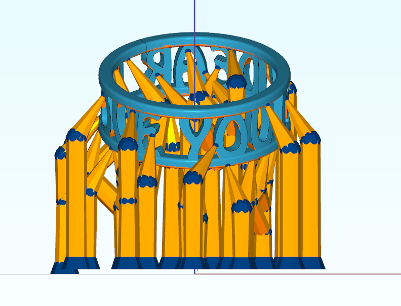
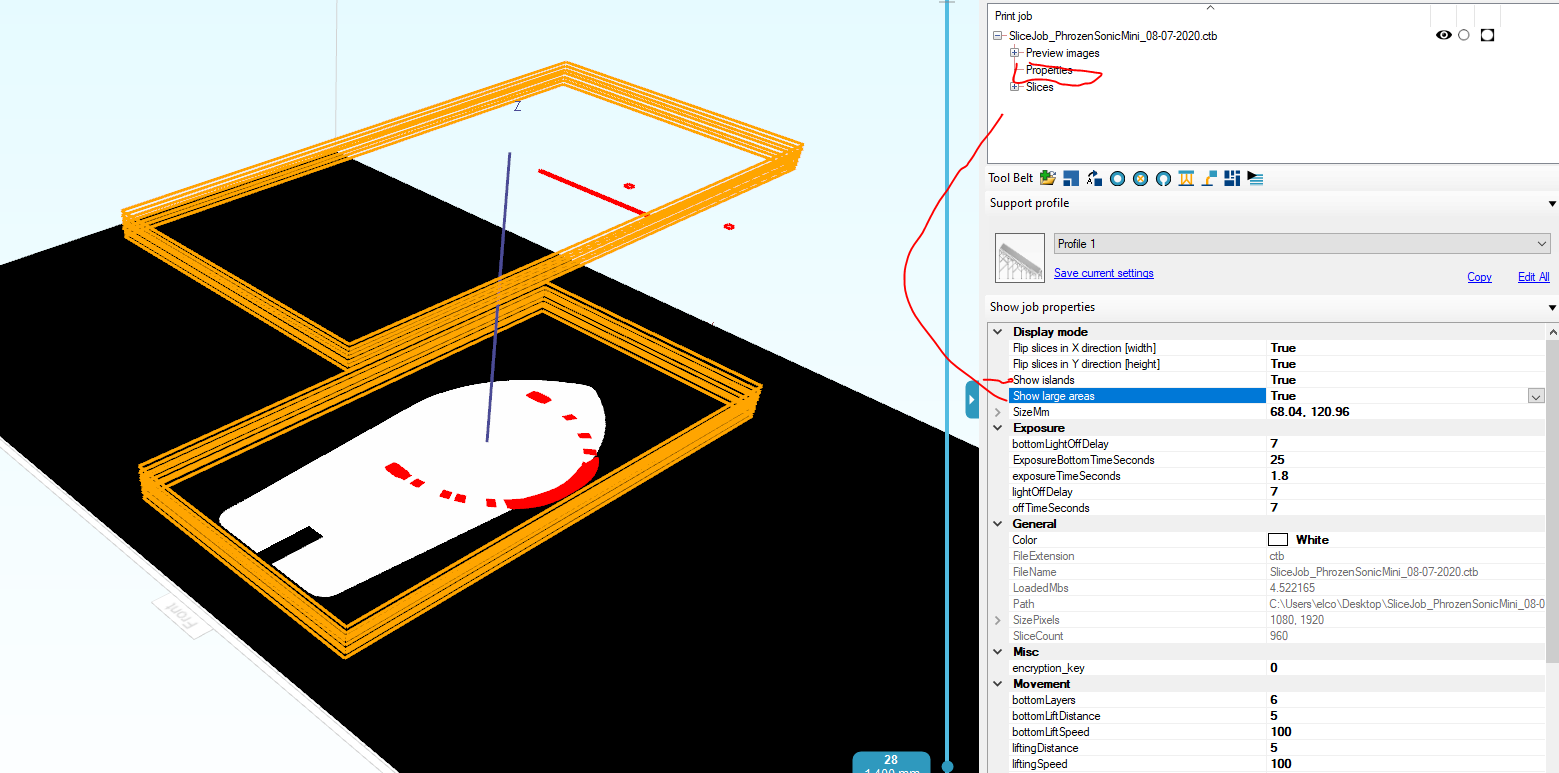
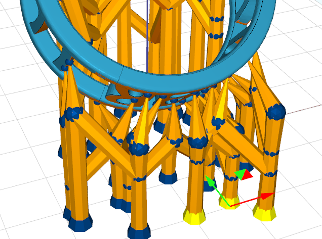
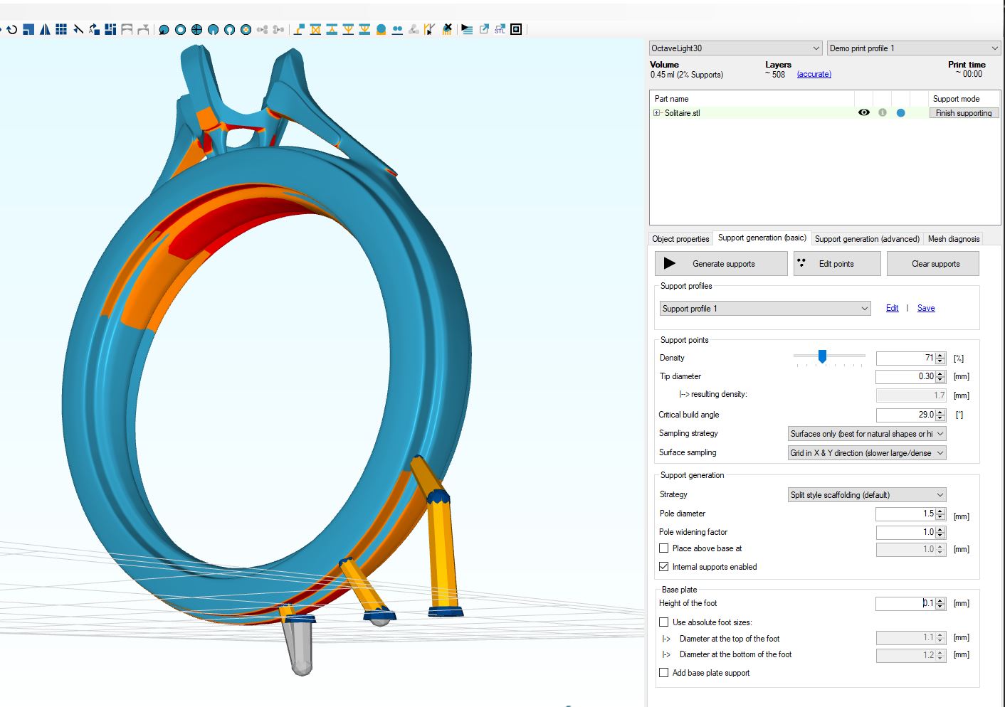
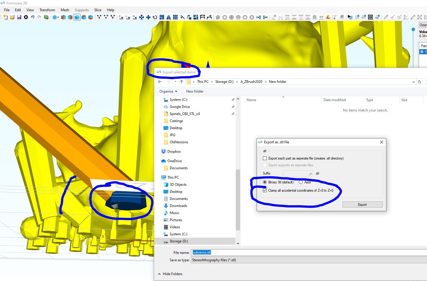
I’ve got a tricky model that isn’t responding well to automatic support generation. I spent a couple hours meticulously supporting the spots that need to be supported and putting the feet where they wouldn’t interfere, then cross-bracing them for strength. Then I printed it and discovered ruined FEP, I assumed because it detached from the baseplate. Changed the FEP, started it printing again, happened to look at the screen and saw that it was printing one foot. Opened it in Chitubox and behold:

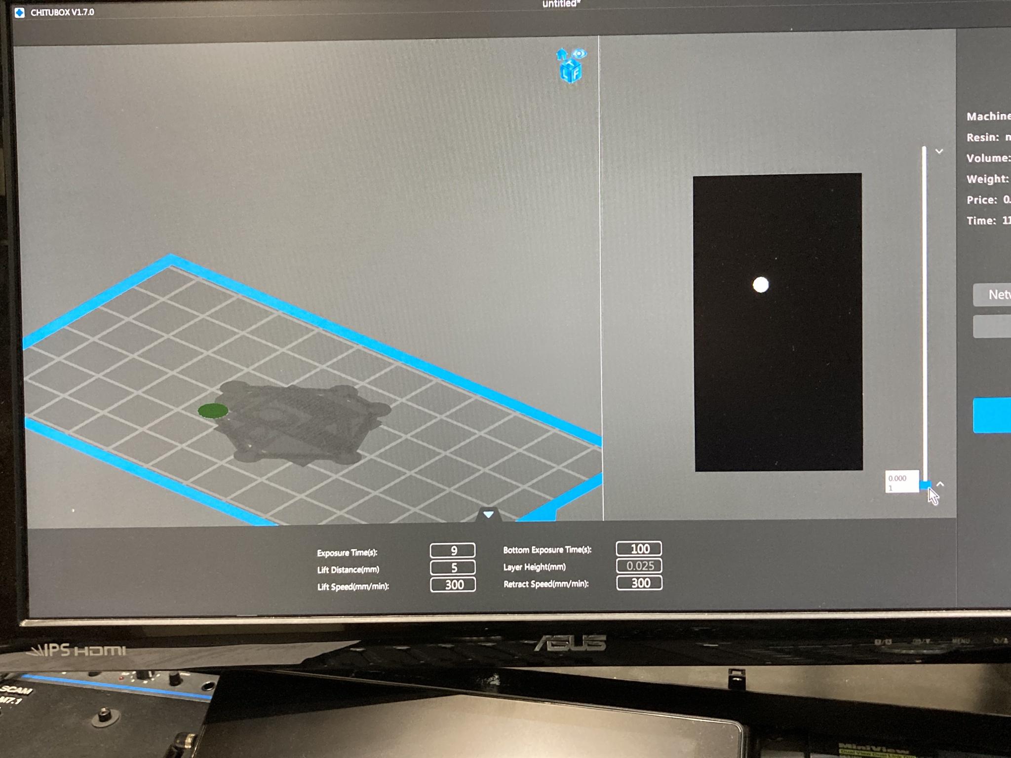
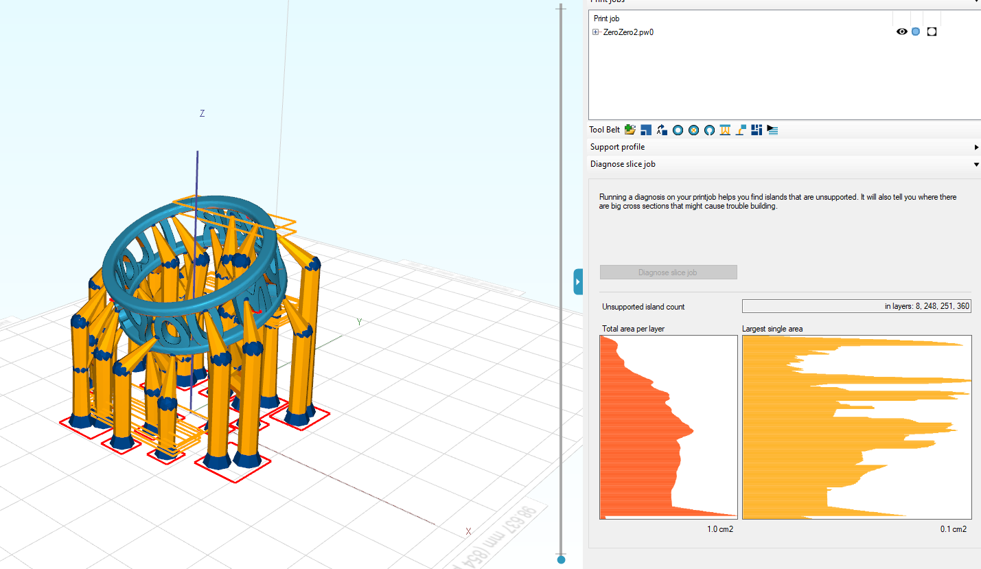
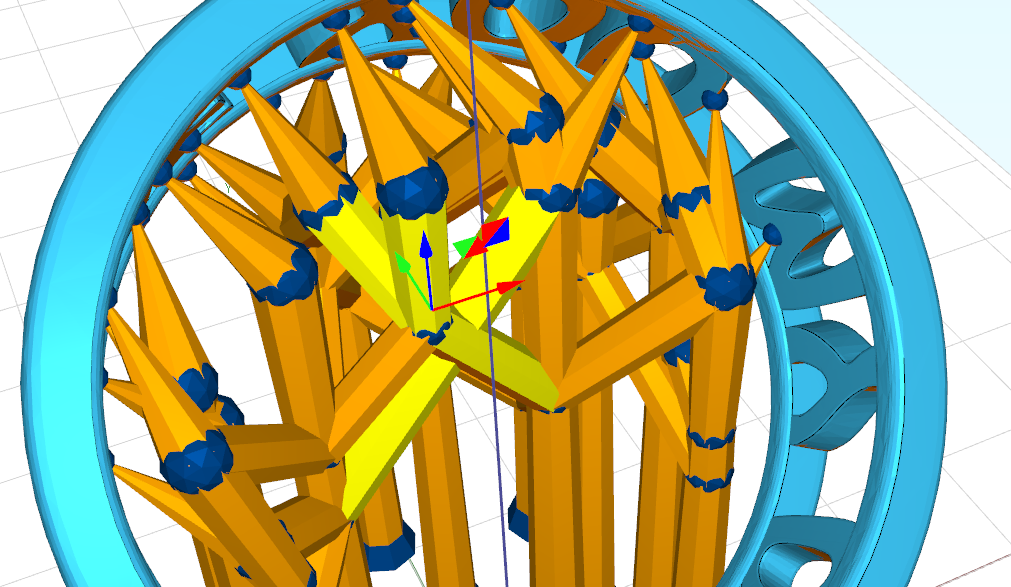
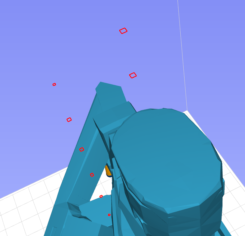
Dig back into the model and found the problem:

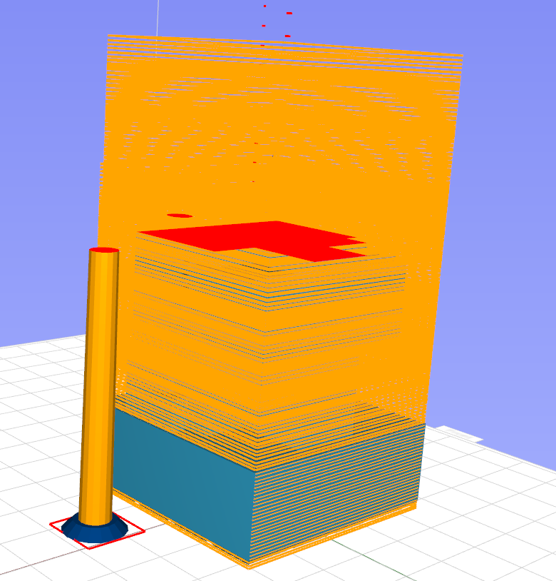
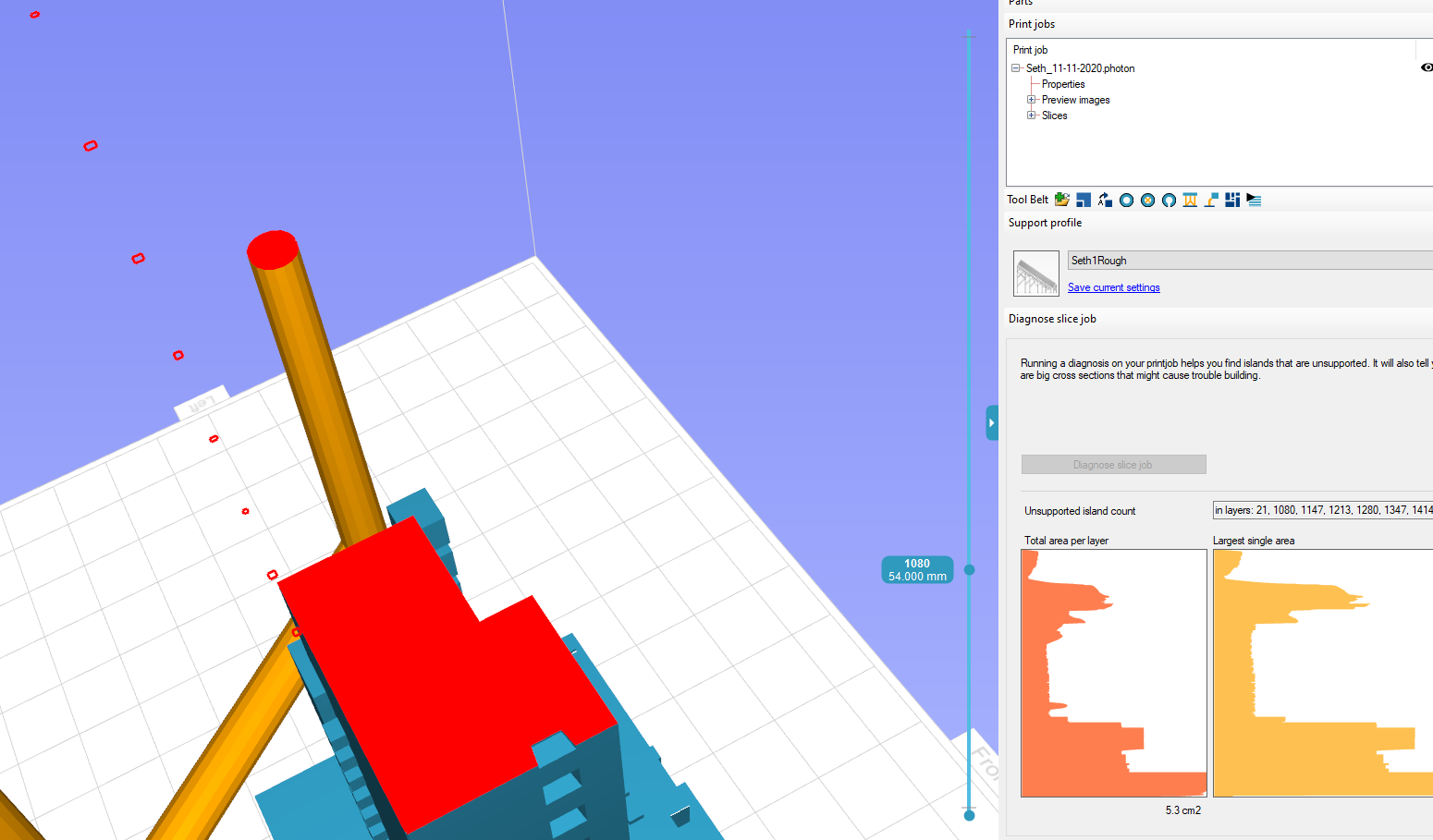
So it looks like what happened is I managed to drag a foot below the ground plane. Then when I sliced the model, it reset the ground plane. As a consequence, I have one support… and then 63 slices of air, and then the model resumes.

Worse, there’s no way to repair this. I can move that foot to “zero” but Formware has foresworn it and colors it gray. It’s not on the same level as the other feet. So I gotta start over.

This seems like it would have been avoided utterly if the feet couldn’t be moved off the baseplate. That seems like an easy fix. Is there a method or workflow issue to prevent this? 'cuz automatic support generation has mostly worked in the past but I got this one model that’s just a total pain in the ass and I’m super gunshy now.


#2

Yeah this is a problem. I started over on the model and it printed okay - I oversupported it so I went back in and took out a few. When I tried to print it again, it had raised some feet half a millimeter. Oddly enough, these were feet where I have two overlapping trees (I saw no way to add new branches to trees, so I just doubled up). One foot was connected to the baseplate, the other was made to float. Worse, when I look at it in Formware everything looks fine… but when I pull it up in Chitubox it eliminates the foot touching the baseplate. Worse, it crashed the printer after a few hundred slices.

The best explanation I can come up with is that Formware is writing corrupt code related to the feet. This isn’t great.


#3

Hello
Had this as well, but I managed to come around this by modifying the foot and support head dimensions.
On some dimensions this problem happened, on some not. But sadly I don´t remember what I had done,
and I don´t have the file anymore.
But maybe you can try in this direction a little bit.

Best regards, Chris


#4

Hi,

I’m investigating it.

Is any one of you using ZBleed correction or Shrinkage correction as a pre processing filter before slicing?

Elco


#5

Another question; to what machine are you exporting?

If you export an ‘stl’ and you slice it somewhere else it might happen that the other software lifts the model.
Of course our error that a foot can get below z=0.


#6

Update:

I’ve just tested with Shrinkage correction is ON it will generate the error if an object is below z=0.

After slicing:


#7

on a side note as it might help diagnose problems; since version 1032 there is a ‘print job’ tool set included that allows you to check the generated printfile. (even to edit the header values)

So i.e. the ring supported in the images earlier diagnosed shows the islands with red squares. Large surfaces are oranges.

(Menu -> print job)


#8

Thanks for looking into this, Elco.

  1. Yes, I am using ZBleed, yes I am using shrinkage correction. I characterize my resins as closely as I can because I’m primarily printing masters for metal casting.

  2. I am exporting to an Anycubic Photon. With the amount of effort and materiel I’ve put through the little thing I should probably upgrade but the little critter keeps on truckin’. I’m exporting a .photon and ignoring Chitubox unless I need to do error correction. So… I’ve opened Chitubox twice in eight months. Formware is vastly superior. You make a great product.

  3. This is in 10.2.9. If you’re looking for stuff to sneak into the next update, “automatically check for updates” and “lock feet to build plate” would be excellent checkable options. :wink:

Seth


#9

Hi Seth,

Thanks for the feedback. Ok so then it’s definitely the shrinkage correction + something below the build table.
I’ve corrected this already in our development build so this will be there in next release.

I’m looking at the ‘locking feet to z=0’.
Probably it will come down to locking the gimball to not have vertical arrows. That would be best to avoid mistakes i guess…

I expect either tomorrow or early next week a fix.

Elco


#10

Great news, Elco. I really appreciate it.

Also downloaded 10.3.3 which apparently has “check for updates” in it so that’s awesome. Question, though - is the “largest single area” bounding box supposed to look like this?

because if so, I think I’d like to be able to turn that off. It also looks like the arrow keys allow me to scroll through layers, which is useful. Is there a keyboard shortcut to jump between unsupported islands?


#11

Yes that looks a bit overdone printing a rectangulage thing… :wink:
I’ll make some logic to turn if off if in >10% of the layers.

There is already a toggle to control the display in the job properties (joblist properties, top menu or rightclick black slice preview):


#12

Regarding the accidental movements below z.
I’ve rewritten the code for what ‘movements’ are available in the interface when an object is selected.

It will now detect what ‘types’ of support geometries you have selected. (i.e. foot, tip, center joint, beam)
Then it will find the union of all movement options for each item.

i.e. you select a couple of feet; it will only show you X, Y and XY
i.e. you select a part

image

A beam in the middle has more options to move:


#13

That’s awesome. I didn’t notice that. Kinda looks like you need to import the slice file, adjust your properties and then analyze - once I analyzed it, changing things got rid of the analysis.

What method are you using to find islands? It appears to find a whole bunch of areas, one on top of the other, that it thinks are “islands” yet have never been a part of the model. They’re out in free space.

This is the top of the model, complete:


#14

Hi,

Interesting, i thought i typed a reply here. Somehow not send. Or i did it in email.

Workflow: yes currently it doesn’t import your slicejob automatically after slicing. To be done.
We are about to redo the slice engine as well to incorporate this.

Island detection: it works with a floodfill in 2D.
Can it be the printjob is flipped in X or Y direction?
Use topview to inspect the layers. Zoom in far enough and you see what pixel is causing the island… ?


#15

LOL that particular slice file was on a jump drive I had to use to update the firmware on my car stereo over the weekend. Curse you IOS 14!!

Make ya a deal - I’ll take a look at it when you push your update. If whatever I’m seeing isn’t likely to be in a new slice engine anyway I don’t think it’s worth worrying about - we already know that this particular method of supporting throws corruptions into the slice file, this might just be them manifesting. It did lock up my Photon twice.


#16

Hi,


I have made a few posts about manual supports being generated under the build plate since about 18 months ago. There is a check box in the export that cuts the offenders off but …There are multiple untrapped errors.
Dragging the support to a more acute angle to clear your model will cause the support trunk to penetrate the foot and bite into the plate. That is because the shape is 90 degrees to the trunk One solution is to make the base of the trunk in the foot semi hemispherical. The other cause was parameterising the min foot height when using very short supports. If min foot height and support height > Z0 to model attach point, the foot penetrates the build plate. Workaround -don’t tick this box or program it to start measurements at the base of the foot==Z0 and warn if the specified support is too long in total.

Regards,
Gary
www.octavelightuk.ucraft.site


#17

I have the same problem with 1.0.3.1 - 1.0.3.3. I use Shrink and Z-Bleed compensation also.
https://www.asuswebstorage.com/navigate/a/#/s/EEDD6C37289C49308A6A8F8E6C3AB0D4W
Elco, check the project, please.


#18

How are we doing on a revision, Elco? Right now I have a choice between scaling and manual supports. I tried a workaround yesterday and it didn’t work; I think it’s gonna cost me a layer of FEP.


#19

Almost there with an update.

To summarize it a bit what we’ll do now:

  • Improve the warning if something falls below the build plate. ‘Below’ should be ‘worst’ than ‘Outside’ (to be done)
  • Limited dragging of supports (or anything with gimball) to the least common set. (so feet can only be moved in XY plane) (done)
  • Fix: the Shrinkage correction to scale from Z=0 as the baseline. This will prevent stuff getting lifted if it was below Z=0 before the correction and thus prevent this unnecasary translation. (done)

I think when I look at the cases of supports below the build plate in Gary’s post; we would need a different suppor t type. It makes no sense at all to have a very ‘advanced’ editable support in a location like that. Guess it would make more sense to have some sort of light weight thin wall that you can scrape of.
Ideas?


#20

Hi,

I’ve checked your file.

I see 2 supports are below the plate. Not good of course.
I looks like a bug in the branching algoritm but it can also be in the correction algitm that corrects for intersections (and thus moves parts). I will check this asap.

Sidenot; I would change your mesh detail settings to the minimum.
You now have a file that is 500mb as there are many supports. This slows you down in every step down the way (editting, slicing etc.)

thx,
Elco