
Currently the implementation of the antialiasing feature happens only in the XY plane. Which makes printing layers easy visible.
I believe there are no hardware limitations to implementing a 3D Antialiasing, ie including the Z axis, a Voxel antialising.
One way I read would be to slice the piece into its three XY, XZ and YZ planes with 2D antialiasing. After intersecting these slices and taking an arithmetic average of the values.
Autodesk’s slicing program apparently does it successfully
True 3D Antialiasing
Gustavo
#1
nzfinescale
#4
I’ve had a play with AA generating slices with photoshop as well as using AA in slicing software incl Formware. . My conclusion is that it is not very good on LCD printers. One reason is that resin polymerisation is not linear 0-255 with gray scale. Thus a GPU AA doesn’t really work in practice on a print. However, even calibrating to get a gray scale that works for resin curing and creating slices with Photoshop still did not really create the expected smoothing. I wonder if this is due to the screen door of the LCD?
In any case, effective 3D AA is a needed killer feature.
formware
#5
Yes i agree nzfinescale; the polymerisation is a non-lineair or close to lineair ( y=ax+b) process.
I think in general any grayscale values cause some type of partial polymerisation and thus some sort of rounding. Our experience was that it’s better than nothing.
But one should also take in account that a pixel only grows outward from an existing object as the autodesk tests nicely show.
Our experience with the lower end LCD displays so far has shown that it’s al a bit ‘unaccurate’. You will not reach pixel exact prints with 500USD machines.
The diffusion of the light when using only a cheap set of spherical lenses is suboptimal. You can never project 1 single pixel.
There is a distance between the screen and the glass as well if i remember correctly.
But it wouldn’t make sense to put an expensive lens setup of thousands of $$ in a machine of 500USD.
I thinks in terms of smoothing something in Z direcion some sort of a dittering filter might make sense to create an optical illusion in z direction. It would need testing
Elco
marc
#6
that’s also our experience and in combination with the chitu Mono LCDs, surfaces are quite smooth in xy-direction. The only stepping pattern left is in z-direction and I hope like the other commenters that this can be improved with z-direction AA.
While it’s certainly true that the light does not hit the LCD and polymer perfectly parallel, xy-AA proofs that it’s worthwhile. Additionally, I’m not aware of a technical reason why z-AA should be less effective than xy-AA. No doubt though, the results will vary like they do with xy-AA and implementing AA during 3D-slicing is more involved.
So a big +1 for 3D-AA 
formware
#7
hi all,
We’ve just had another random discussion/brainstorm about this topic.
We think 3d AA has some potential and it ‘might’ work.
So we will do a test upcoming weeks if it’s feasible in terms of processing speed and print quality difference.
I say ‘might’ because even if you could mathemaically solve it within reasonable computation time; it’s still a question of how well it comes out off the machines. The pixels grow in non-lineair way starting from the previous exposed parts. So I would imagine that for 1 side of a sphere it works better than for the opposite side.
to be continued…
Elco
TomMartin
#8
Thank you for taking up the gauntlet! As already written here it is better to have any Z-axis AA effect than none. It would be up to users to play with other printing settings to have best possible results.
formware
#9
Hi,
I’ve figured out the math/logic… also came up with a way to test it. So that will happen next few weeks.
I’ll post the results as soon as I have them here.
Not sure yet what it will do with slicing time yet but it will for sure increase it by at least factor 2.
Elco
marc
#10
great! it’s arguably the most advanced feature in any non-industrial slicer, so an increase of the slicing time of up to 20 is certainly acceptable, at least for us.
formware
#11
Hi All,
Just a short update on this topic. We’ve implemented an algoritm that works smoothly numerically.
Algoritm is verified in the 3d viewer visually in all directions with overlaying the printjob output.
Also the slicing time is acceptable. Still pretty fast for a 2k screen. Non optimized.
I’ve attached some image below.
We’ve done some first test yesterday but the results were that it doesn’t make any difference.
The tests were done on a Creality machine (low end) with an Anycubic Grey resin.
At this point i’m thinking variable layer height might make more sense for these lower end machines, with all the downsides it might have.
On the other end we’re thinking that these good old DLP chipsets might have more capabilities in the end to use gray scalling in Z direction.
- Would love to hear your thoughts on this.
- And if you have a high accuracy DLP machine if you are willing to do a test?
@nzfinescale did you have similar results?
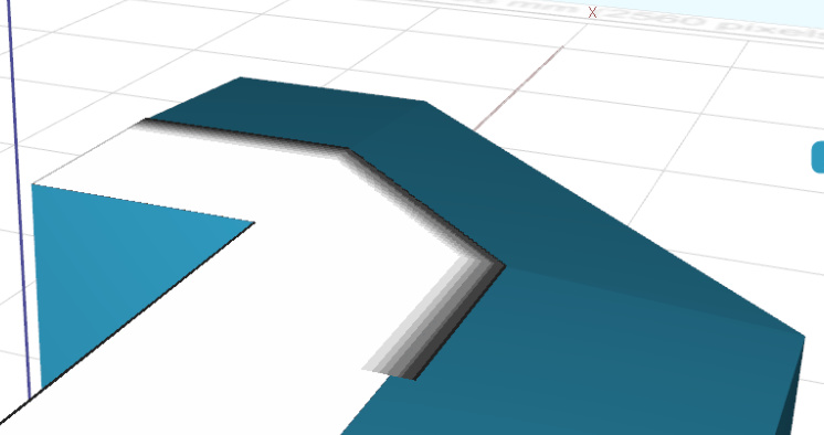
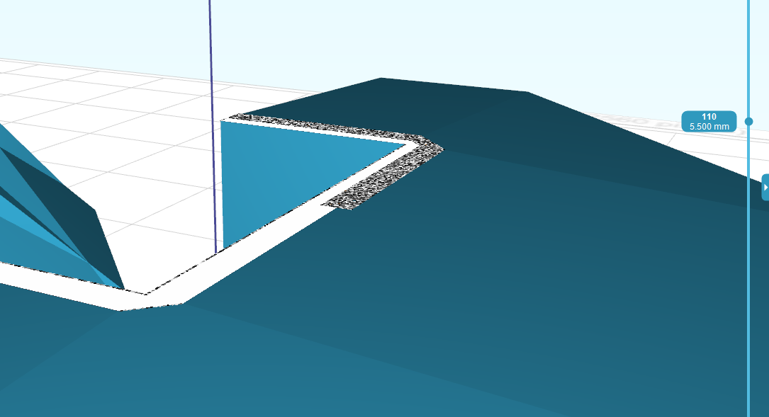
1:16 surface angle:
sphere top:
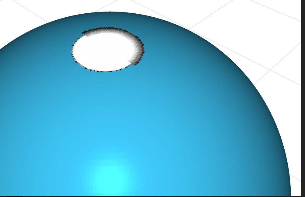
dittering applied instead of AA in Z direction

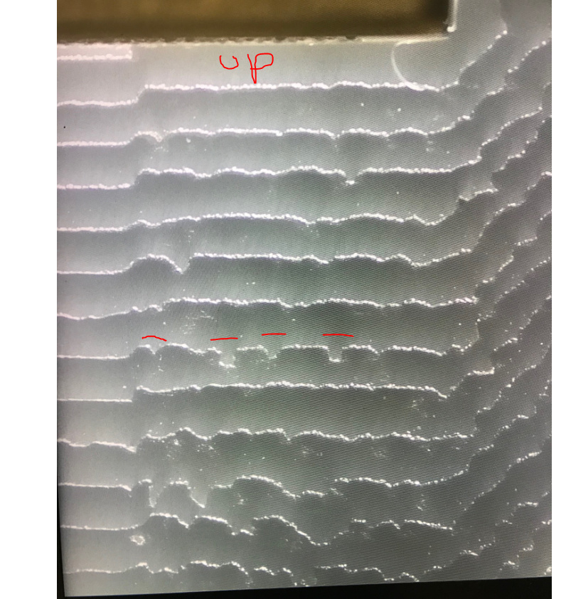
Print result. Left half of the table is Z antialiased.
You see a very little different in light over the stair steps. Marked red.
formware
#12
After some more research we found this interesting lecture by an Autodesk Ember team member:
It has more or less the same findings we had so far.
Plus 2 more things to try;
-
correction curve for any gray scale output. (like @nzfinescale mentioned)
In their case a DLP beamer uses gamma correction on the blue channel -
general noise filter seems to do something in Z direction.
Elco
nzfinescale
#13
Great to see progress.
In terms of what I can contribute in terms of experience: The Solus DLP ran it’s own software and I was not able to do tests on it. I’ve retired that machine now. My tests have been on a Sonic XL4K.
In macro photography of prints you can see individual voxels quite clearly. So 1) I think the lens system is generally adequate, and 2) introducing some fuzziness with a diffuser has been demonstrated by others to improve print smoothness. I guess the reality is that a soft edged circular projected pixel will produce a smoother result than a hard edged square one. I imagine that it is better to do this in hardware, but I have not had chance to do this yet, although I have obtained parts. It wouldn’t surprise me if AA is a lot more effective after som optical blurring.
nzfinescale
#14
Since I last looked at this UVTools software has come a long way. This now allows some testing of concepts in a fairly easy way (not in AA per se, but image manipulation to simulate AA)
It seems to me that 3D AA is good in theory but:
- With LCD printers there may be some optical work (ie diffusers) needed for it to work well. This is a bit theoretical but I have a feeling correctly exposed imaged pixels are a bit too discrete for the subtle effects of pixel growth from partly exposed adjacent pixels to work well. Should be OK in Z on subsequent layers, but likley not so good on preceding layers.
- Correction of the gray scale to linearise polymerisation is a must.
- We need the software - which you seem well advanced on.
I have a second printer on order, so will hopefull find a window to have a play.
Lawrence
formware
#15
Hi Lawrence,
Thanks for the feedback. I’ve found the youtube movie above highly interesting. Hope you find the time to watch it.
Interesting to hear about teh Sonic XL 4K, we have one as wel so perhaps I should switch to testing on that. Haven’t printed on it yet except dry runs for software development.
Regardign the macro photography; my business partner is also planning to try that. Put an LCD screen under a microscope and check pixel alignment. On second thought we are not 100% sure what LCD screen is inside the Creality machine we tested, perhaps not even a Mono screen.
to be continued.
Elco
TomMartin
#16
Hi Elco,
I have looked at the photos of the printed objects and I think it is promising. Not enough to solve Z steps completely but to limit them and facilitate further postprocessing with use of sanding sponge and glass brush. Currently I use Phrozen Sonic Mini 4K and with Z layer set to 0.01 - 0.02mm and 4K XY resolution it could be quite noticeable effect. Is there any possibility to test this 3D AA somehow? Do you plan to share Alpha or Beta engine for testing?
Best,
Tomasz
formware
#17
One last update before the weekend.
Today we’ve done some extra tests a noise filter like in the youtube link above.
On the contrary to what Autodesk finds with a DLP chipset we find no effect yet in our low cost LCD printer.
First a microscope image of the Creality’s LCD screen when turned on:
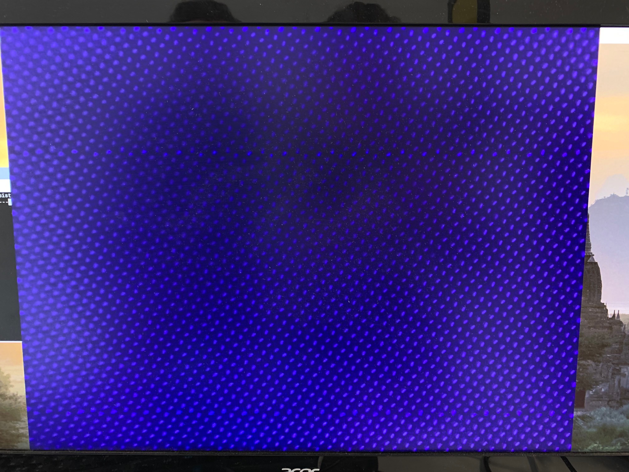
Most probably this is not a Mono screen, but a regular RGB screen with a certain blue filter.
Only blue pixels are used. It’s clear there is a large distance between each pixel.
Then the test print in close on a 1:16 slope with the slices overlayed and 100% noise applied on the anti aliased levels:
This is the slice in topview:
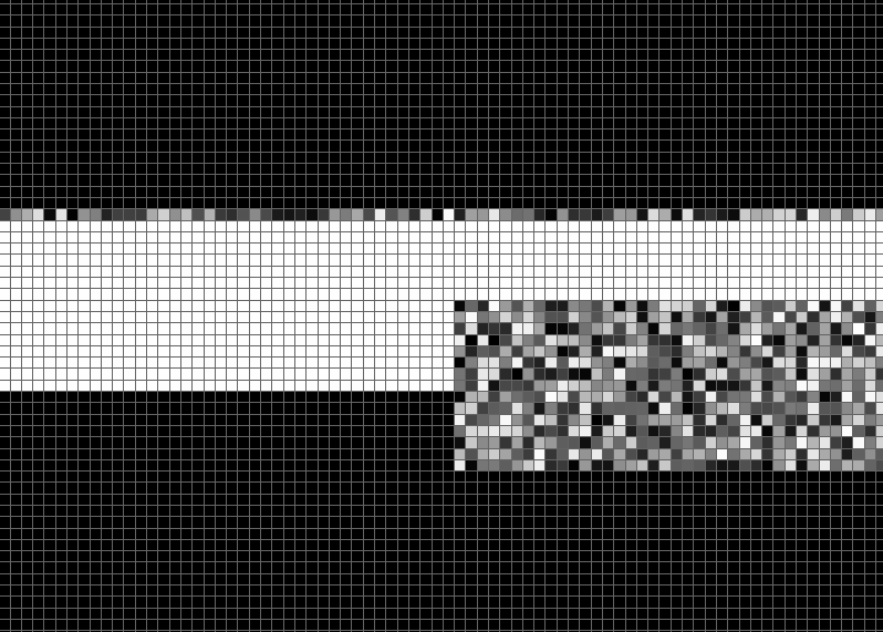
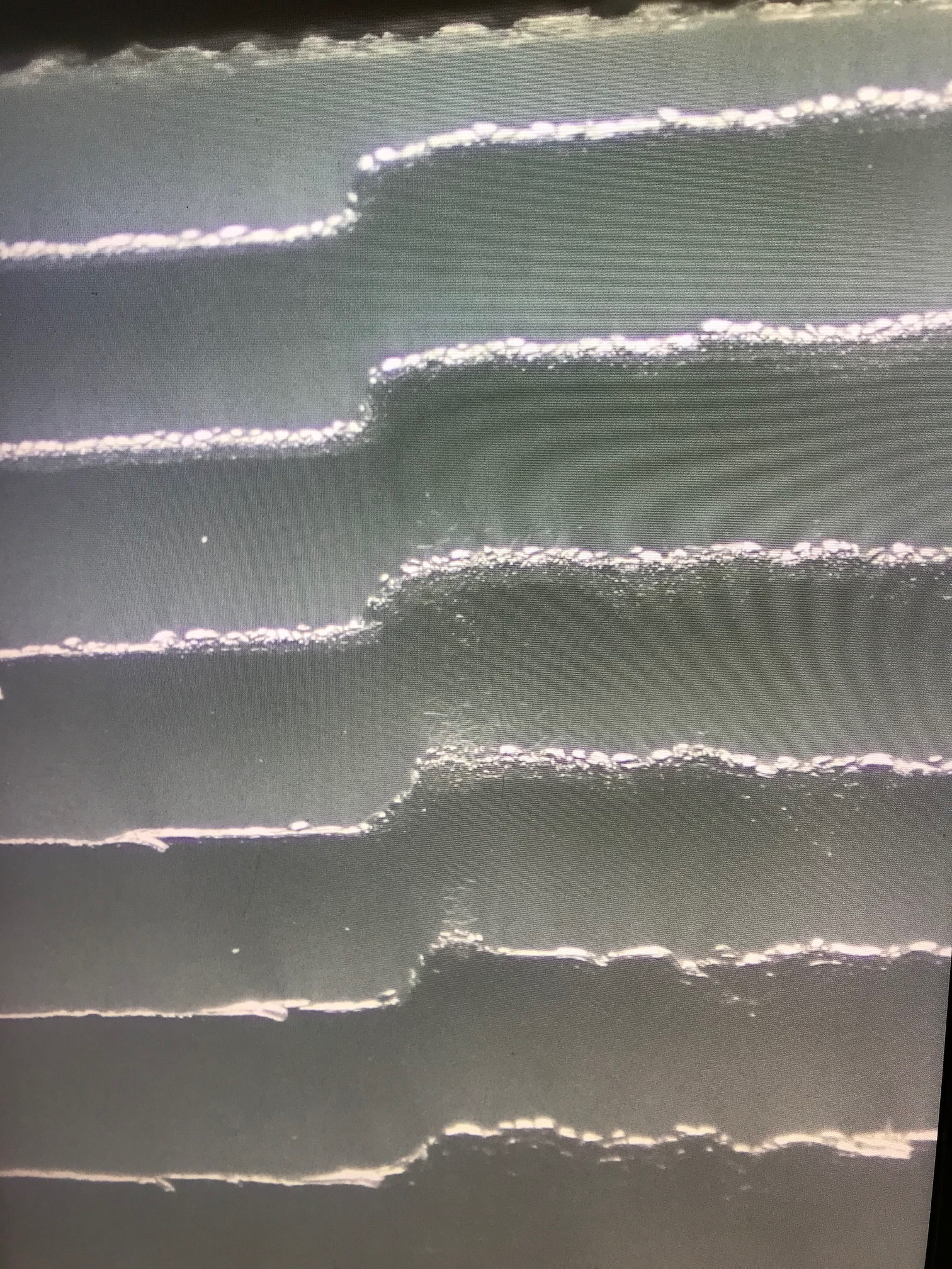
And this is a microscopic view of the actual top layer.
Conclusions:
(valid for low end LCD printers with regular RGB screens)
-
You can clearly see that exposing individual gray scaled pixels has no influence in Z direction. The layer border is just moved back entirely by the part that contains the noise. No noise pixels are printed correcly
-
Anti aliased pixels on the XY edges work. The upper part of the photo shows the upper vertical border. You can clearly see the noise effect there. Makes kind of sense; XY anti aliasing has an effect. Z anti alasing alone doesnt, the pixels don’t solidify.
-
We assume this entire effect takes place because you need to ‘over expose’ to solidify 1 pixel through a small ‘pixel’ lens to connect to it’s neighbouring pixels. So partial pixels next to other partial pixels are virtually impossible…
One thing we are curious about is how the exact pixel grows. Starting from the FEP or from the existing object. Any thoughts/reasoning?
We have some other idea’s about how to trick the printer but not sure if the CTB boards would allow this. I guess we will continue on the Phrozen machine to see if there is any difference. The screen pixels look more promising there.
Last a nice picture of the top of the sphere. Top half of the image is with noise on the Z AA pixels.

Support for really small parts
"Mask Wizard" and advanced calibration
formware
#18
@TomMartin Yes i’ll publish some of the algoritms in the next release. Needs some UI here and there.
I think it might make most sense to put them in some kind of ‘Lab’ modus as they are not garantueed to work and very dependent on what you are printing and what kind of printer you use. So it will always be a bit ‘use with caution’.
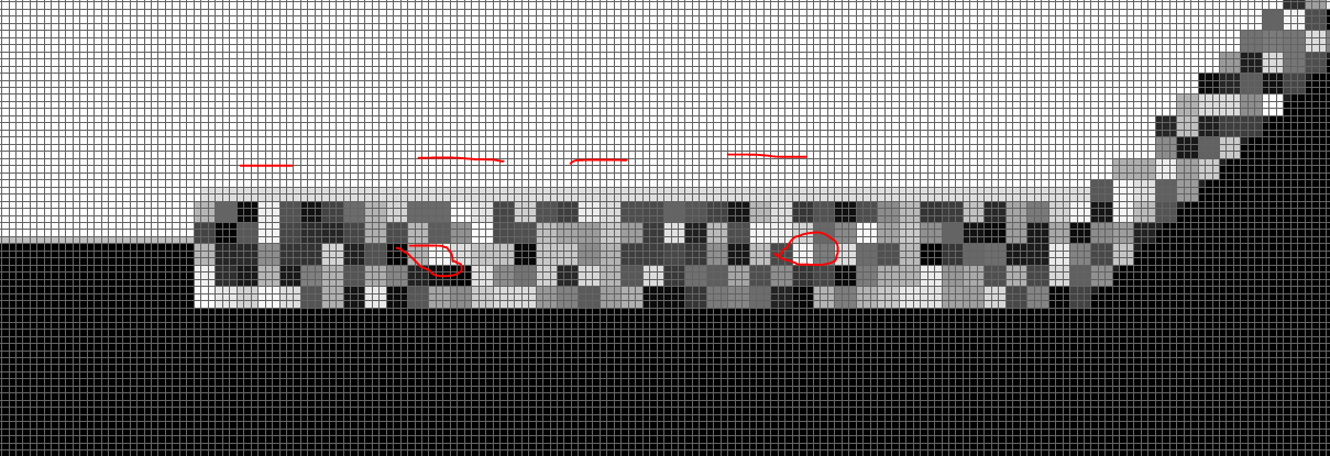
I did one more test today with the Creality machine to find out what the minimum feature size actually is and if we could find some use in the Noise filters. So to do this I modified the noise filter to generate 3x3 blocks on the Z antialiased surfaces. Below you will see 2 screenshots of what this actually does on 50micron layer thickness.
So the conclusion with this type of screen is you would typically need 6x6 pixels minimum to get something exposed. So your minimum feature size would be +/- 300 x 300 micron.
An interesting observation is that it seems that you can get small shapes more square with puting a white pixel block outside the corners. (red squares). Seems to be the trick from the lithography world.
This 300 micron finding also makes sense with our printing tests where supports of 0.3mm absolutely would not print on these screens.
to be continued…
formware
#19
fyi, 3D anti aliasing was released in V1038.
I consider it experimental; in the sense that I don’t know on what machiens it will give what effect. It’s being tested by several OEM’s as I type.
Elco