True 3D Antialiasing


#25

I tried to reply sooner but my account was locked to 3 replies so I had to delete one and wait a day for it to actually go, I’ve got more pics too but can’t post them, anyways…
I did it myself. originally I used blender compositor to compare two sliced images and make a variable blur that would blur far more for areas with big layer differences so that they would get big gradients and small layer differences would have smaller blurs, this could perfectly smooth things like spheres and lenses however if strong blur was used with this it would eliminate details, a compromise between detail and smoothness could be met but it was never ideal because this was post-processing so it could never know what should be sharp or soft.

So then I made a system in blender that would slice 3d models in blender and get all the necessary data for perfect gradients. This can smooth out most angles while keeping sharpness, if just used on one layer it won’t reduce detail but will instead increase it, for the best smoothness as shown in some of these pics overlapping some layers helps, at least with a clear resin, I haven’t got this extra level of smoothing to work with pigmented resins yet, but normal vertical AA works with it, AA isn’t really what it is, it’s not post processing but I call it VAA for ease. I have even got it so dialed in that I can slice suzan the blender monkey and print it on one layer… (excuse the scratches and damage my fep was worn)


#26

Hi Tom,

I’ve upped the setting…you should be able to post now. this is a forum system we didn’t make ourselves :wink:

That’s very impressive!
Is the monkey transparent resin as well?
So from what I read between the lines it might very well be the printer type and resin combination that will do the trick then… What printer do you use?

I’ved tested the last version of our output on an anycubic D2 (as it has a DMD chip) and thus more crips pixel boundaries.
What I noticed was that the rough edges like my images above are gone, they are much much sharper. Also the 3d anti aliasing does work for some part; but it might introduce actually a more shallow layer step,
So instead of the normal layer step which would ook like this:
_|–
You would more get something like:
_/-
Which would make it more visible :thinking:

So it seemed to only work half… my next test was going to be to add some kind of lineair output filter to the grey scales; as the resin is supposed to have a threshold for solidification… did you use this as well? Or you use just 0-255 gray values?

I tested this with a default grey pigmented resin by the way…

Elco


#27

Well the most unique thing about how I did it is that I’m not using a DLP printer like you or the ember team, it’s just an old saturn 1 with a thick screen protector so the bloom is like 4-7 degrees Minimum. This isnt ideal because it means the light could be less concentrated by the time it reaches the last layer as compared to when it passes the fep and first touches resin. Most people even very knowledgeable people in the resin printing community think 3D AA can only be done on industrial printers, they assume that on consumer printers the resin always cures from the fep up but it just isn’t true unless the layer height is too high, I can do 50um with pigmented and clear but at 100um clear it cured from the fep up, I haven’t tried 100um with pigmented yet but I’m sure it would be worse.

The monkey is pigmented resin, the reason it looks perfectly smooth despite me only getting perfectly smooth results with clear resin thus far is that the monkey is printed on one 50um layer! The pigmented resin I’m testing with atm is 3DMaterials superfast grey, I’m going to test either elegoo space grey 8k or ST fast grey abs like next.

For the gradient modifications I firstly get a good 0.0-1.0 value gradient and then apply a compensation curve, I was using my own curve but now use one more similar to the one showed in the long ember video, except they do it all in one curve. I split it into three, firstly the curve compensation to fix how resin doesn’t cure uniformly, gradients cna look bumped when they shouldn’t be. Then I apply the upper grey offset, usually with a proper exposure 90% can still produce a full height layer so I squash down the highest value of the gradient so that the gradient starts actually going down on height when it should rather than remaining at full height until it gets to 20% into the gradient. Then I do the same for the lower grey offset because of course resin doesn’t start to cure until a specific point which from my tests seems to be about 60% at 50um and 40% at 30um, this of course varies with printers and resins but when properly exposed it doesn’t vary as much as would think at least from my limited testing.

Also I have all the major variables like upper and lower grey offsets and compensation curve strength and layer overlap etc hooked up so that I can vary them per model to have dozens of tests print at once. And I can also do things like use a normal pass to do different settings for different angles, eg when angles get steeper the resin doesn’t produce tiny gradients, no just acts like normal XY AA where the edge just moves about so a different curve to account for the higher bloom or a wider gradient (larger layer overlap) or a lower upper and higher grey offset etc could be preferable, I can adjust all these settings dynamically with a normal map.


#28

I use gradients like these for calibration, its a linear gradient from 0-100% in 5% steps. at one side there is nothing so you can see how far down the gradient goes by where the edge there stops and at the side with the numbers there is a full white area besides the gradient so you can see by when the edge between that and the gradient goes where the gradient starts at the high end which can be used to figure out the correct upper and lower grey offset.

This is adjusted with a upper and lower grey offset and the ember curve at full power. As you can see the edges between each 5% adjusted step is more visable at the high end meaning either the upper grey offset or the compensation curve is too strong…


#29

This (image above in previous post) is from a print with the same settings, you can actually see that the gradient curves down and you can see shiny gaps meaning the gradient isn’t covering the top of the last layer, meaning the lower grey offset is too low (there is no grey offset on this example) causing the gradient to stop before it should, or the upper grey offset of the last layer is not strong enough and therefore when it should be printing at say 80% height it’s still at full height making it impossible for the next layer to cover it unless layer overlapping is used. If I havent made it clear, to do layer overlapping I just have it read more depth data, so while it slices every 50um or whatever, it can take depth data from any depth, such as 3-4x the layer depth which produced super smooth results with the clear resin.

So then here is a gradient where I lowered the Lowe grey offset a tad, perhaps 5% too much because it starts to get rough. But anyways the compensation curve is at half power here and it’s working much better, as you can see throughout the lines are equally visable, it’s hard to get the right angle with the camera but they are all there so I know the gradient is even without needing a microscope or anything.

With the first version of the slicer due to it being post processing variable bluring it couldn’t slice something like this so I made the gradient in photoshop but now it is the slicer so to make the sliced images for this gradient test I literally made an array of steps going 2.5um up to 50um and it can slice that perfectly. That’s how the monkey was sliced, squashed it down and just sliced it with one layer.


This is an example of some different lower grey offsets.


#30

Uploading: 20230807_041305.jpg…

This is an image printed on one 50um layer


this is the same layer just printed about 3 times, it’s easier to see the image but it’s actually not got as good range as the single layer, like if you zoom into some areas the shadows and highlights are squashed as if there was an S curve applied, meanwhile the single layer has all the correct values mapped correctly showing how accurate it is.

Now for this type of stuff variation in printer exposure can be a problem so I put my printer in its side and took some photos to make a mask which turned out really well, it’s a far sharper mask than results I’ve seen from someone making a machine to move a uv sensor across the printer. However A uv tools applies masks incorrectly, it uses an absaloute operation rather than multiply which it should use and there is no multiply function in the whole thing so I have to use blender compositor to apply the mask which is slow, but what’s worse is that the mask applied to images can vastly slow down how long the printer takes to load the images while printing. But what’s worse is when running a full plate of VAA tests I’ve had the printer glitch out, and it was basically impossible to print a large complex image with lots of grey values like with the images above because the printer just glitches out and the image flickers and moves. This is the most limiting aspect of consumer printers for VAA it seems, and because of this I’ve not been bothering to use the mask I made because it would increase the chance of total failures from the printer just being to slow to handle the complex images.


#31

Here are some images I wanted to post earlier:


And here is the result of my photo mask of you were wondering:

ps I’ve hit the limit of posts for a new user on this topic again

Also I’ve just found out that every anycubic print including for the D2 when saved in UV tools limits the 255 input to steps of 7% so only about 14 total values, and you can only use about half the range for VAA so it’s more like 7 values. Perhaps your slicer can output anycubic files with less compression? Or perhaps its a limit of the printer put their to avoid the same glitching I get when I go past the printer’s computer capabilities by sending it large layers with lots of complex greyscales.

Also I found this out while testing with somebody who has an anycubic printer, at 35um with a 4 layer overlap I managed to get almost layer-less results for them with high pigment resin, comparable to the 3L result I got with clear resin but far more detailed because of the more detailed resin and printer (34um)


#32

@formware hi Elco

Where can I switch on 3D antialiasing and configure it?


#33

For existing printers; do it in the settings file.
C:\Users<winuser>\AppData\Roaming\3D_FORMWARE3D_{741D228E-AC07-40C2-A9DC-560B18A54F03}

I need to turn the ‘box’ on for every printer; will do when we add the non-lineair output filter. I think that is the missing last piece of the puzzle.

image

kind regards
Elco


#34

Hi Tom,

Thanks for your extensive report. I think it’s pretty amazing what you’ve achieved.

From what I read between the lines;

  • we need to add a non-lineair output filter, that is easily customizable. Seems that is really making a difference
  • and some way to configure this output filter with a gradient piece.
  • the mask -> we had the same thing with several printers. They can’t cope with many different pixel values. I dont understand why; as most data is run length encoded and should be written directly into a framebuffer for display. So i think it’s just sloppy programming on the firmwares…

When i find the time next weeks i will try and make some tests on the anycubic D2. (DMD) I have good hopes that we will see some result there as well with such a gradient.

kind regards
Elco


#35

@Tom, i upped all settings in this forum again to 50 per post… bit annoying sorry.


#36

Here is a link to download a sliced file with a gradient test for a D2
https://TDrive108.ezconnect.to/portal/apis/fileExplorer/share_link.cgi?link=BmLJgwulUpLBrFARD07bPA

It should look like this:

with 5% steps.

but instead, because every any cubic file I made in UV tools gets limited to 4 bits it looks like this:

with 7% jumps and some values merged because it only has 16 value steps, and if like most setups you can use about the upper 50% of that then that means you only get about 7 value steps so you won’t be able to get super smooth stuff like this:

(the difference isn’t super easy to see here because we are going from 5% steps to 7% steps but imagine if I had a linear gradient with 1/256 steps then it would limit that to 1/16 steps (7%) so that would be more dramatic, same result though, it’s 4 bit, I had somebody with an anycubic printer print a monkey like this and I don’t have a pic but they said they could just about see some small lines due to the stepping due to it being 4 bit.

I wondered if they do this so that they don’t get the same frame buffer issues we both had with masks, but if you had it too, and that was on any cubic machines then that is super weird considering they are literally running at 4 bit, unless they aren’t 4 bit and it’s just UVT that’s outputting 4 bit and you can make 8 bit any cubic files???

But you should still be able to do normal VAA… I’ve had two people test my VAA with anycubic printers

One has had good results:


(I forgot to add a no VAA print to his test prints so what you are seeing is a weak 1L VAA vs 4L at the top which was very good for him and then at the bottom a 1L vs 3L 35% lower grey and 45% lower grey offset. IIRC this was 35um so not directly comparable to my 50um prints.

This is the other person who tried VAA with an anycubic printer:


For some reason here the gradient started at a super low power, like 7% when it should start at 40-60% and it didn’t start with a super thin layer it started fairly thick, no idea what’s going on here.

here is a very high res collection of a bunch of my VAA tests with pigmented resins ST fast grey and 3DMaterials superfast grey on the right. You may have to open it in a new window or something to zoom in properly idk.
Here is one of the best


Still far from the clear resin results though.

Also while I originally used my own curve to simply things I just took a screenshot of the curve from the ember video and stretched it to to be 1:1, they included a grey offset but I wanted to do that afterward.
I tried to just use their math function but I found this to be easier and better.


I just made a curve that looked similar and set it up so that in the material properties for each object in the scene I can change the curve factor, the higher offset, the lower offset, the layer overlap, the blur/aa amount and I am experimenting with trying to get higher angles to look good by doing things like having settings change depending on the angle via a normal map so I’ll add settings for that too and whatever else I need.

image

ps some of the prints I posted earlier were negatives for printing, turning my 3d printer into a 2d printer…


for this one the left half is dark because it didn’t print properly there because the frame buffer issues just wouldn’t print properly so I tried to split some layers into like 2-4 parts and print one part at a time, if I do 0 lift height the printer does a normal life ignoring me, if I do 10um it works, it looks like more than a 10um lift but still far lower than if I put it lower, I’ve done stuff like this before and it was alright but here it just didn’t print the layers properly.

Also I tried to show this earlier but the pic wasn’t great… here is ST fast before corrections
(the two bigger ones start at 50%)

and here is the best I’ve got it after corrections, see how even the steps are as you can see by the edges between them.


#37

Hi Tom,

  • It concerns me a bit that of 2 other users that tried is 1 got a complettely off result. Meaning either the hardware is completely random or worn. Or he made a mistake with the parameters…
    So i think I will test it myself as well with this output filter to see what i get :wink:

  • The anycubic file formats changed over time. When they started in 2018 they didn’t have any anti aliasing; just black or white. When they advanced they made a format with simulated anti aliasing; which is basically 4 layers of data compressed into a single layer. So a pixel could be 0, 64, 128, 192 or 255. It was a way to trick their hardware that could only handle black or white. They exposed 4 times 1 image in 1 layer so to say…
    Later formats they changed it to a 4bit runength encoding. So that is 16 different values. And is what you seem to be using.
    I think they thought it was the maximum that would be needed; or wanted to save a couple of bytes of their files…
    So yes; if you need 50% exposure to start with you are only left with 8 different values. Still; on 50 micron layerheight; that should mean a different of 50/8 ~ 6 micron steps. Should be pretty good…

  • Thanks for your input regarding the correction curve. We have a formula-editor and parser in the software. So i think i will just allow a formula to be entered for the correction curve; or alternatively a datatable where you can input 255 values. I mean; in the end it’s only replacing bytes with 1 out of a table of 255… choice is not unlimited…

  • Ill also think of a testpiece STL. I rather have a simple STL that can be used as a testpiecce then a seperate image i have to generate and hardcode in the software… as not all users use this kind of features (yet)
    In the past I made the mistake to program to detailed stuff and wizzards into the software which only benefit a small portion of users… and leave many others with questions of how to use it.
    I think in general you only need to know the upper and lower curve limits; that would already yield you a pretty good curve. And perhaps in between we need a little curvature instead of a straight line.

kind regards
Elco


#38

I’ve had a couple more people try it, those two I mentioned are just the ones using anycubics, also I’ve tested a range of resins including recently I tested elegoo 8k space grey at 25um, this is a very high pigment resin and the gradient I got looked just like any other

so it not working well for that one guy is the exception not the rule. And it could be because of that stuff you mentioned but I sent him files sliced for version 517 which is the newest and still not good.

For test parts, first I print the gradient to get an idea of the range and curve power, then I print a variety of the slope tests and 40k tests that I’ve posted here, I can send you the stls for those of you want. Also with the gradient it’s not hard coded, it’s an actual model with a stair case 50um high with 2.5um steps (or scaled to whatever layer height) and because I’m using a depth map not sub sampling my slicer can easily and accurately slice each step correctly, and then I can do the curve and grey offset corrections and apply it both to the gradient and actual models and it just works.

On the curve point as the ember team showed

curves are neccisary for accuracy, all resins tend to create a kind of round gradient when it should be straight and this needs to be compensated, from my expirience the curve they use can be too much for some resins, I’ve used it with a factor of 0.5-1 depending on the resin, 0.75 would be fine for most though. It’s more important than the higher grey offset because as soon as you add a curve compensation the higher values will drop and so you will see that higher grey offset is not as neccisary, because of bloom I think higher grey offset is always useful but like if you are properly exposed then 10% high grey offset should be fine, I dont think the ember team used one at all. Also don’t go crazy with maths, the ember team tried to use formulas to fix everything as if curing resin was a natural process that should hold true to like they did a really simple formula for steep VAA and it was close but still there was a wobble that they could have easily compensated for and fixed perfectly if they did a more form fitting rather than pretty curve.


#39

Hi all,

Some updates here. No idea if people are still actively reading it.
I’ve made an interface in our development version of the software to setup a correction curve:

Next i’ve made a test piece along Tom’s work; but programmatically (sizes can change) and with the bytes values instead of percentages. (was easier for me). So the left side of this testpiece is actually a gradient in 1 layer, which is 50 micron in my test. So at ‘15’ the piece height is 50 micron lower then at 255.

Below the numbers there is a 50 micron step, from low to high, so you can see where further exposure makes no sense (high end) or less exposure makes no sense (low end)

When sliced with our 3d anti aliasing activated output the result of the most important slice with the gradient will be this:

The initial print test (anycubic d2, 4 bit unfortunatley) resulted in this:

Which clearly shows the layerlines starting around 150-160 grayscale value.
I’ll update the correction and print a new test later, but first have to code/create something to get the prints better of the build plate… this is a bit unworkable.

Elco


#40

So, continued with the next test on the anycubic D2. With the non-lineair correction filter turned on. Just a simple y=ax+b correction like in the image above.

The slice output with 3d anti aliasing + correction filter looks like this:

The print result clearly shows the rectangles are now all filled.

Another thing that can be noticed the surface is a bit more rough; this is probably because it’s not touching the FEP anymore… the surface underneath the letters is pretty smooth.

Next up a sphere with these settings.


#41

In the properties of anycubic files in UV tools there is a use full greyscale property and a grey and grey max count property, unfortunately UVT doesn’t let you change this but I’ve asked the dev if that’s possible

I have got better results with pigmented resins, still not as good as clear but very good. Too much to show it all here, if you hop onto the lychee discord I have a thread in there discussing more if you want
here are a couple examples

I’ve also tried compensating for the layer overlapping I’m doing and I haven’t dialed it in yet but that already shows signs of adding detail previously just unavailable. I’ve explained more about this in my thread on the lychee discord


#42

Hi Tom,

Thx. I tried a sphere as a last example last friday. I noticed layerlines at the lower boundary… so probably with 50 micron layers that would mean still a step of 25-30 micron left.
I think below that level there is just no exposure at the build table. My theory would be the pigment just prevents it.
I’ve ordered 3 more different resins, amongst others a clear one.

Anycubic is 4bit, we discussed it and we think it’s because of the DMD system it uses. It has a native 720p resolution, but it does something called XRP, which is basically shifint the optical system so it increases resolution 4 times. But this probably means they took a shortcut (or necessity) in the datapath. So intest of 8 bit they ended up with 4 bit per pixel. We didn’t reason long enough but it could also be because there is otherwise no mathematical solution as you are basically overlaying pixels… anyhow. Check here if you want to see how this works under the hood: https://www.optotune.com/pixel-shifting

So the Saturn 1 is an lcd printer right?

Did you do any other modifications?

I read somewhere in the beginning that you said ‘overlapping’ layers?
How many pixels overlap do you have between gray shades among layers?
When I’m back in office i’ll post some detail pics of the top of my sphere; i’m curious how yours looks, perhaps the true 3d anti aliased shape coming from our slice core is just not aliased enough yet…

Elco


#43

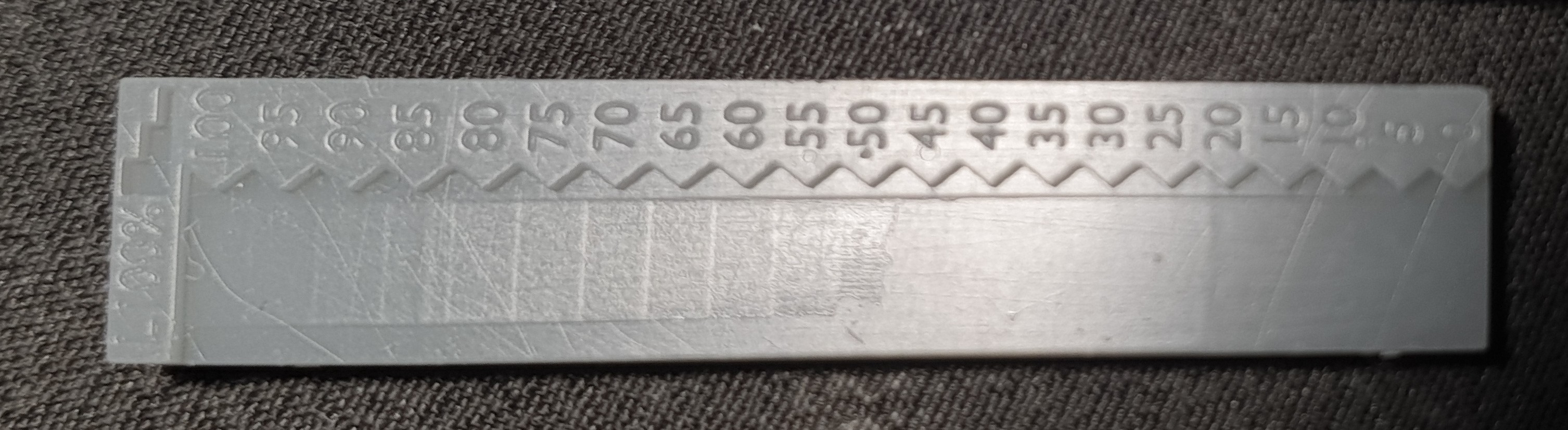
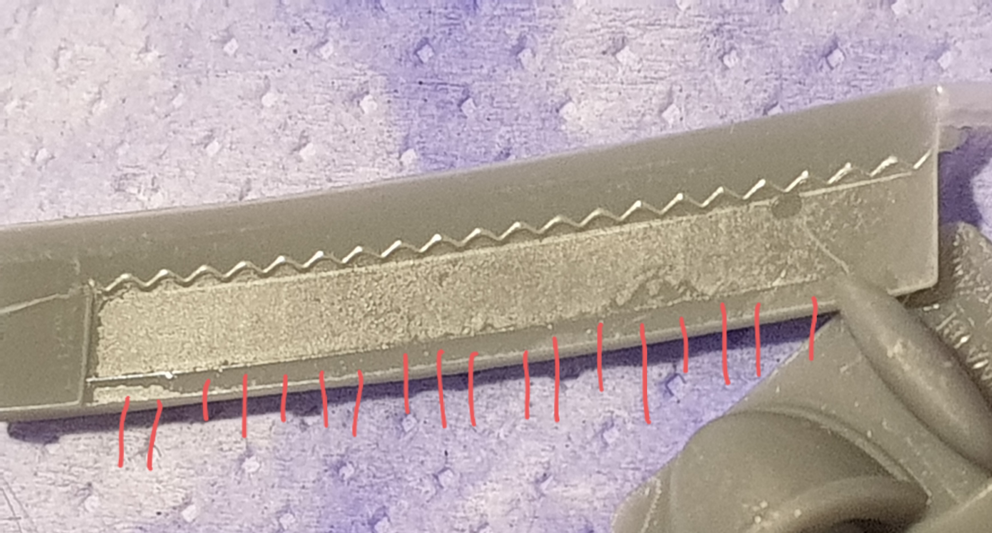
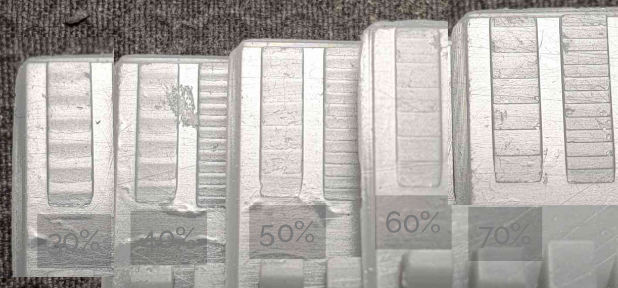
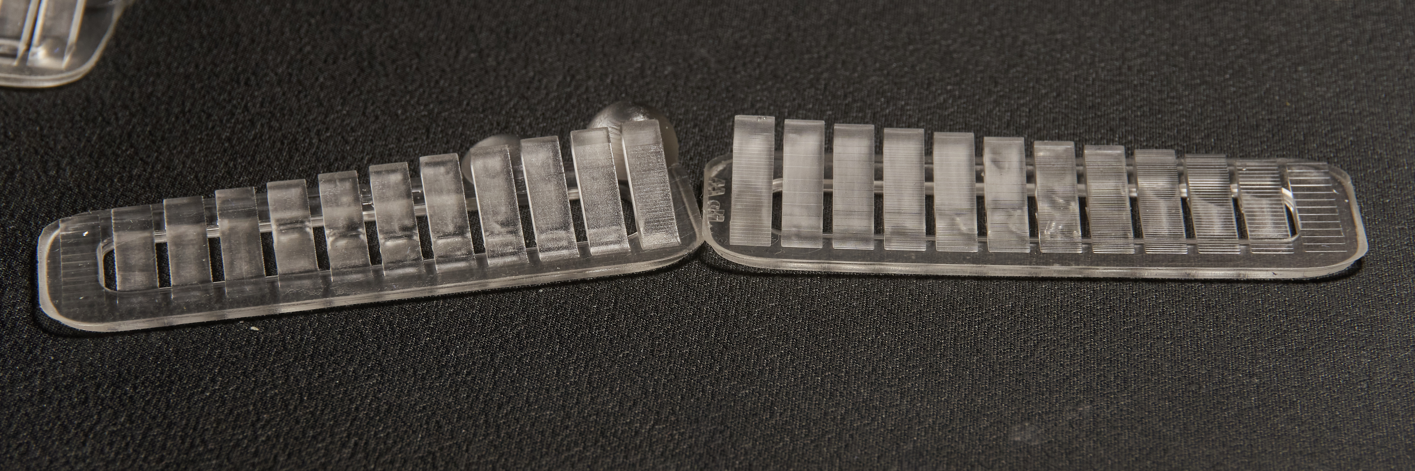
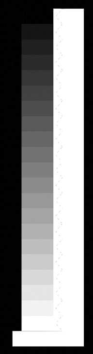
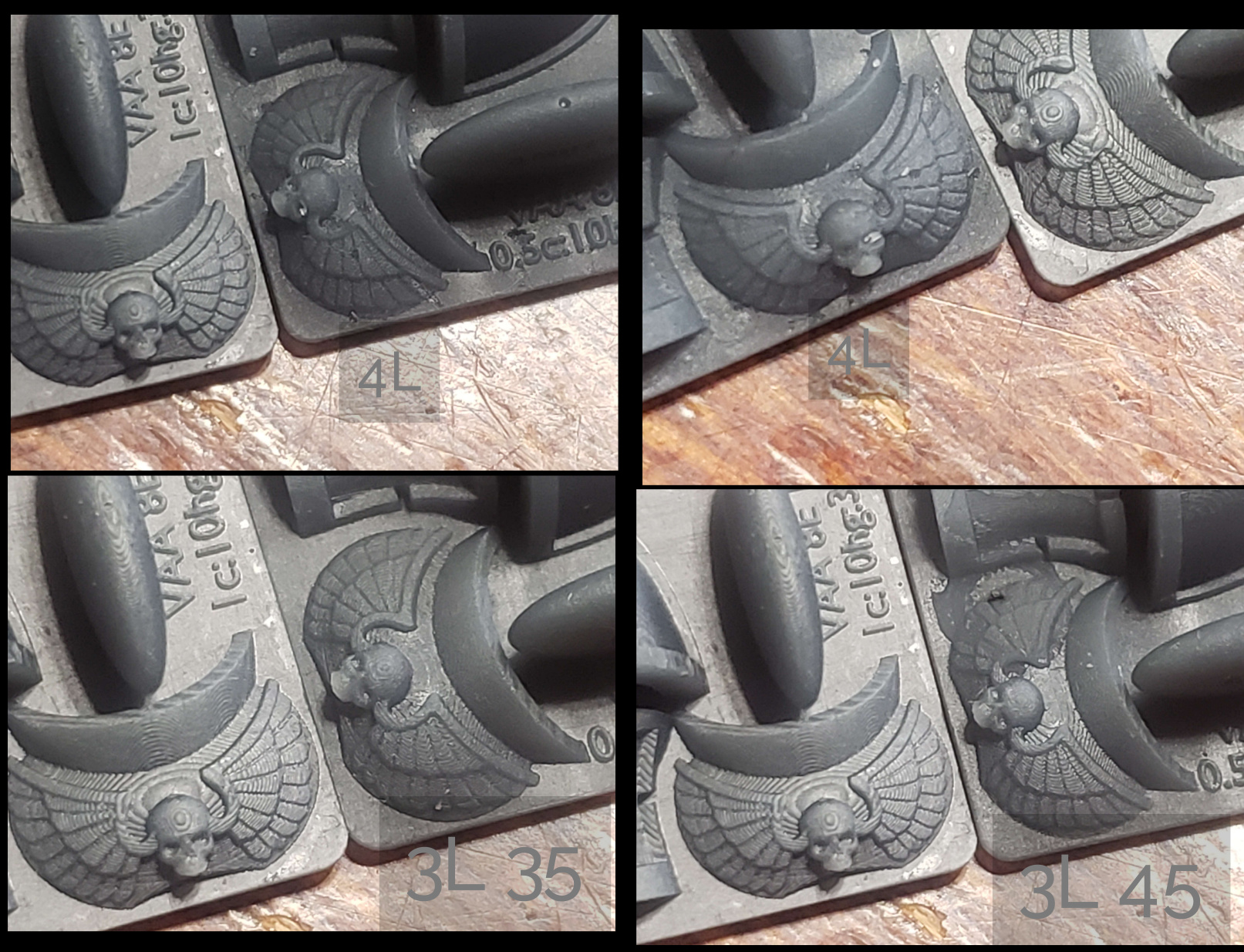
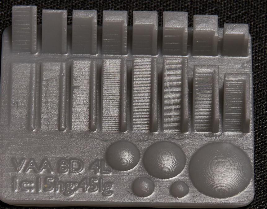
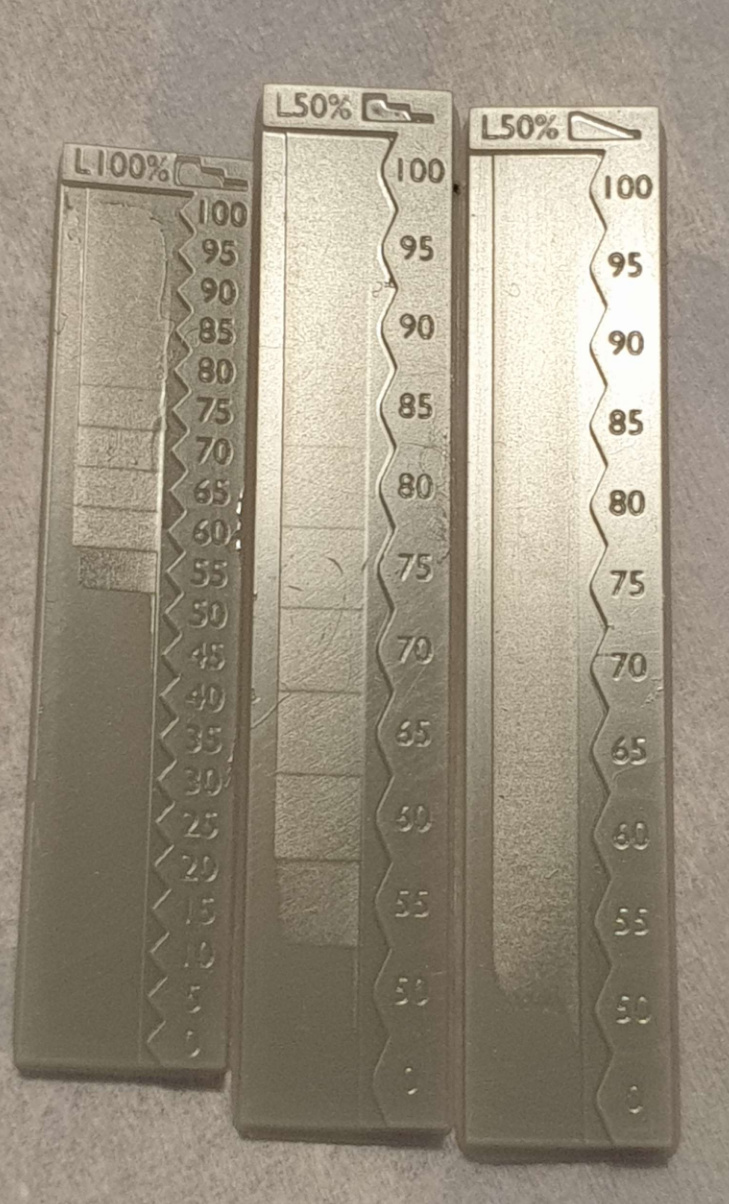
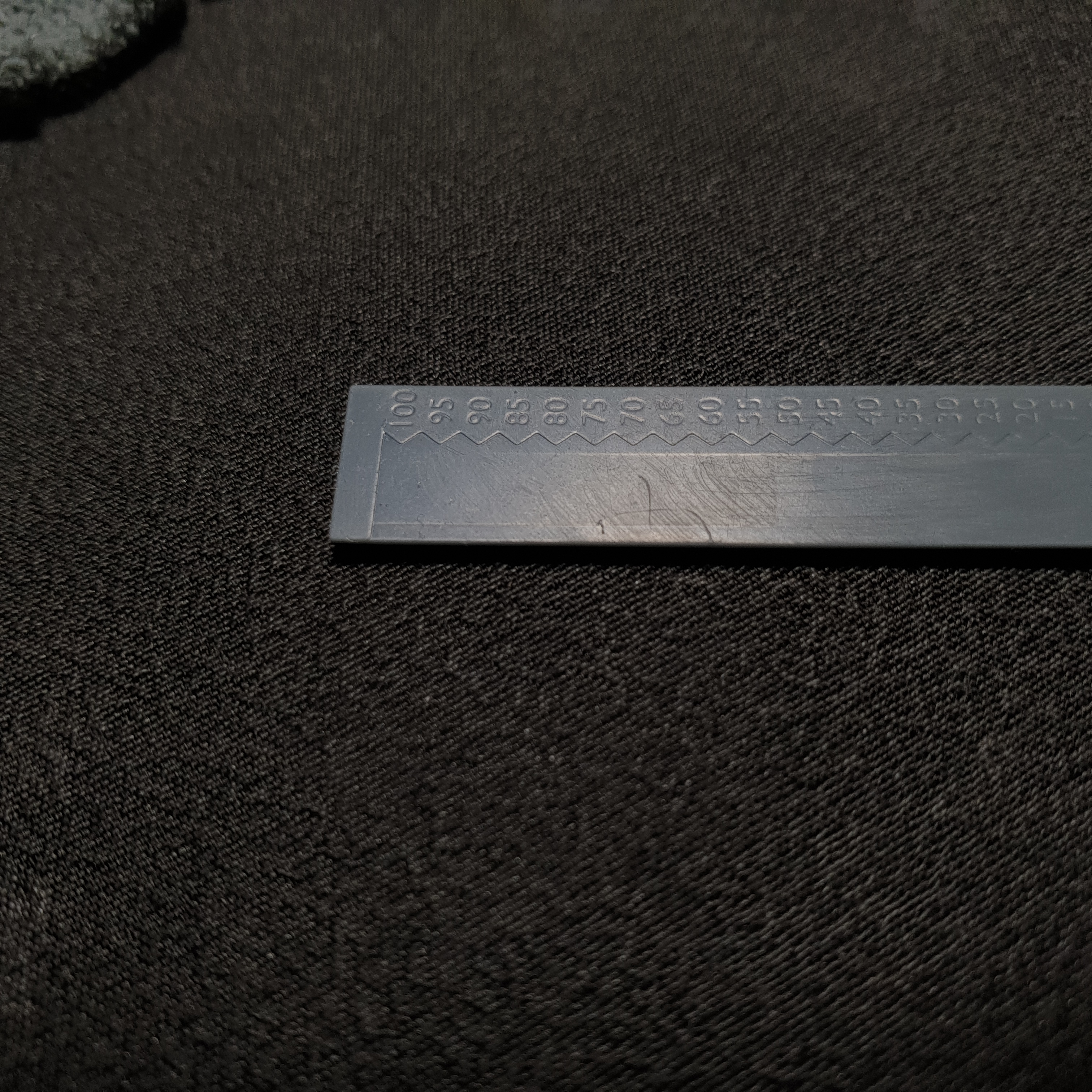
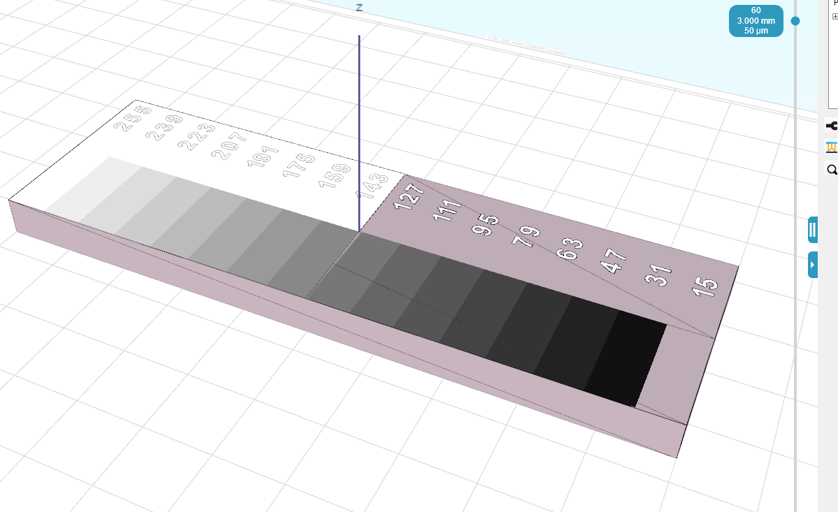
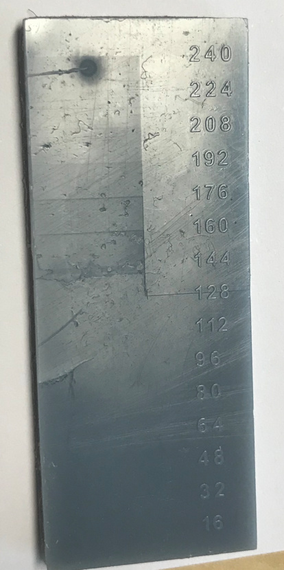
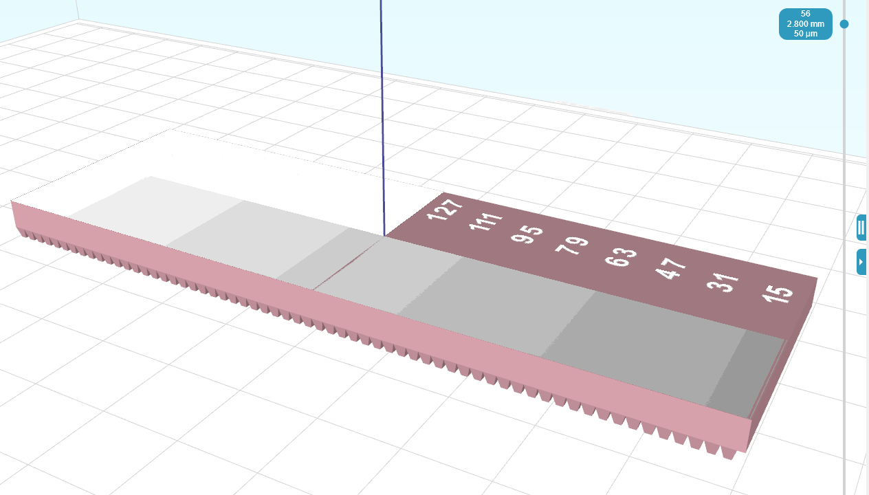
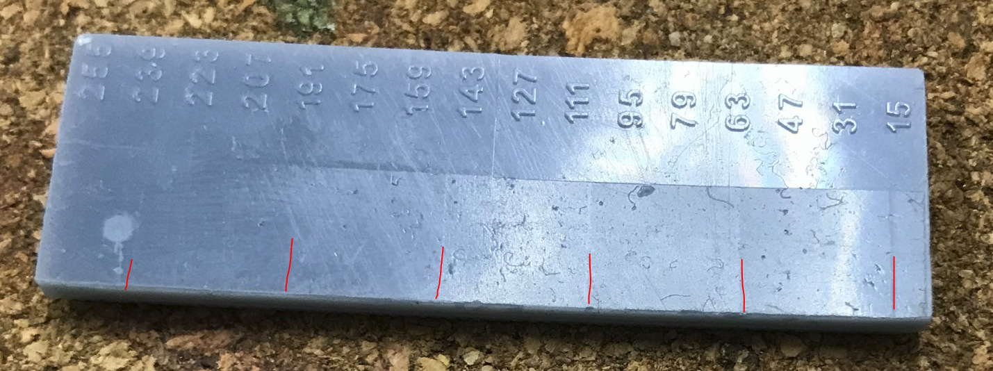
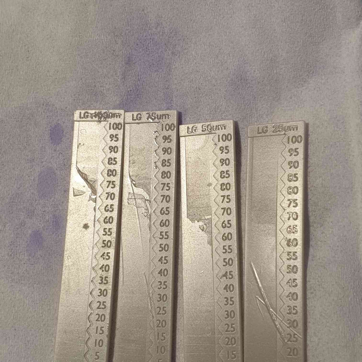
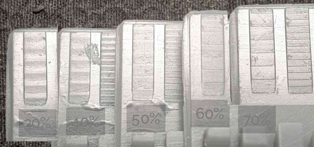
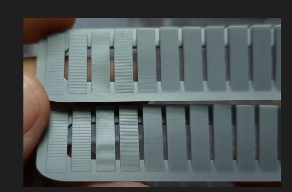
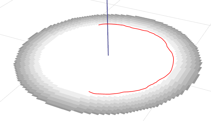
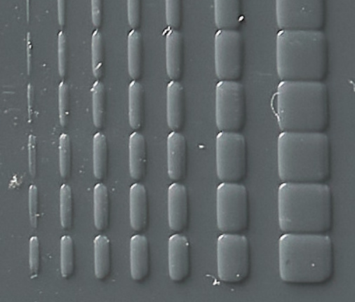
Here is a group of different linear gradient tests I did recently, I actually set up a .ctb4 file so that it did all these different layer heights on one print by printing at 50um and then getting to a certain point and lifting 25um to do the 25um gradient but blank on the other ones, then lifting another 25um to do the 50um etc. As you can see 25um with my saturn 1 was silky smooth, the last layer on that isn’t 25-30micron, it’s stupid small, however as the layer height gets higher the end gets more abrupt as the resin starts to cure from the fep up rather than plate down. Interestingly even at 100um ar like 85 there was some area where it did cure from the previous layer down, not fep first, but not for the lower intensities. However from the fact that there was even a tiny bit like that it shows that with 80+ intensity I can actually print previous layer down on my printer at 100um, the problem is that with a normal layer exposure time that intensity almost builds a full 50um layer thickness, but because we can see it did start from the previous layer at that intensity, it means the same intensity but shorter times would actually yield a thin layer at 50um. I thought that more direct light would cure plate down at thicker layer better, and while I can’t test that because I don’t have a more direct light printer, from this it’s clear that better results at thicker layers can be achieved by using a far higher intensity printer or by an idea I’ve had which I call semi continuous printing, I can’t remember if I explained this fully here, again I have a thread on discord about this, but basically the idea is to go to a certain layer height eg 50um and then cure a few very thin partial layers to build up one layer. I’ve done some tests with this and it worked but not consistently, at the time I couldn’t do 0 lift, anything under 10um would default to a normal lift height which makes multi exposures a pain, but I discovered in the G code I can just change M8070 to z0 and then 0 lift heights work so I will have to do more testing for this stuff at some point.

So yeha you might have abrupt issues because the layer height is too high. You also may have them because your lower grey offset is too high, I found lowering it 10-15% from the linear gradient lowest value was a good spot. And yeha the 4 bit of the anycubics will also limit you because if you are only using half the values thats like 7 values which is not much.

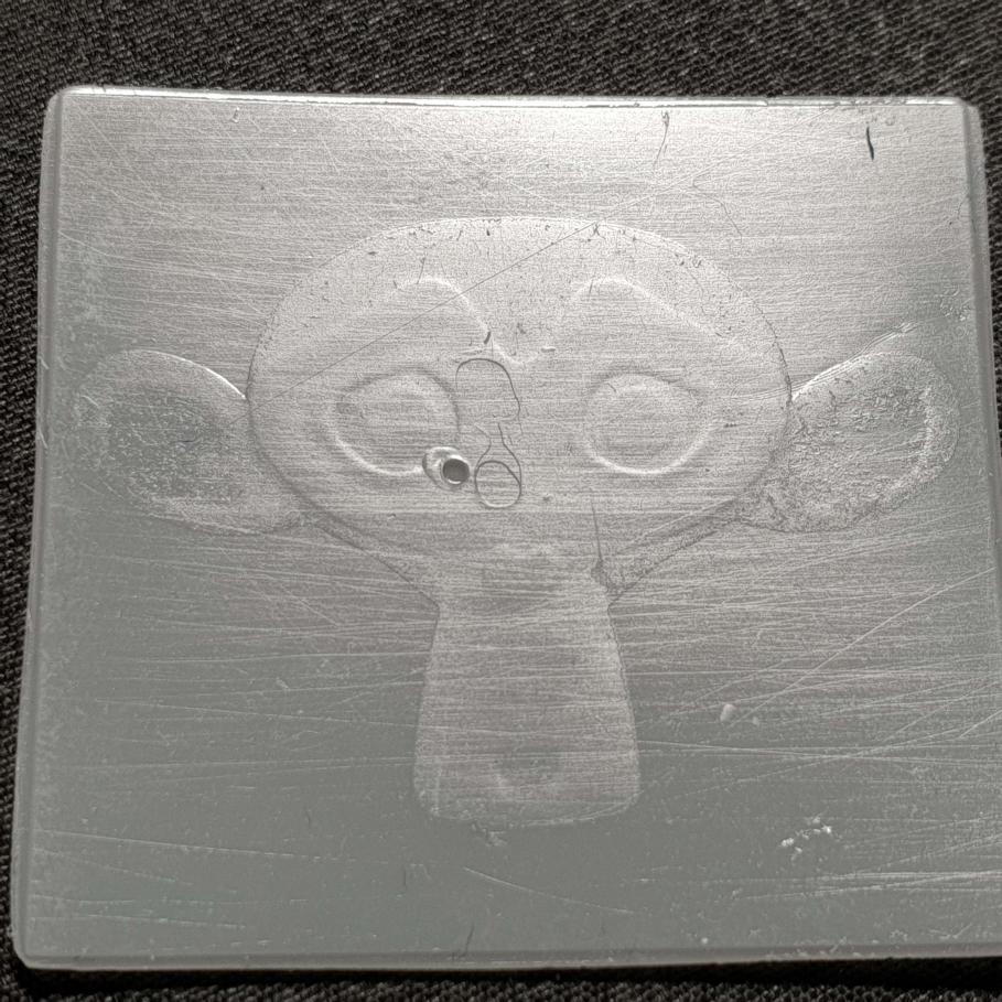
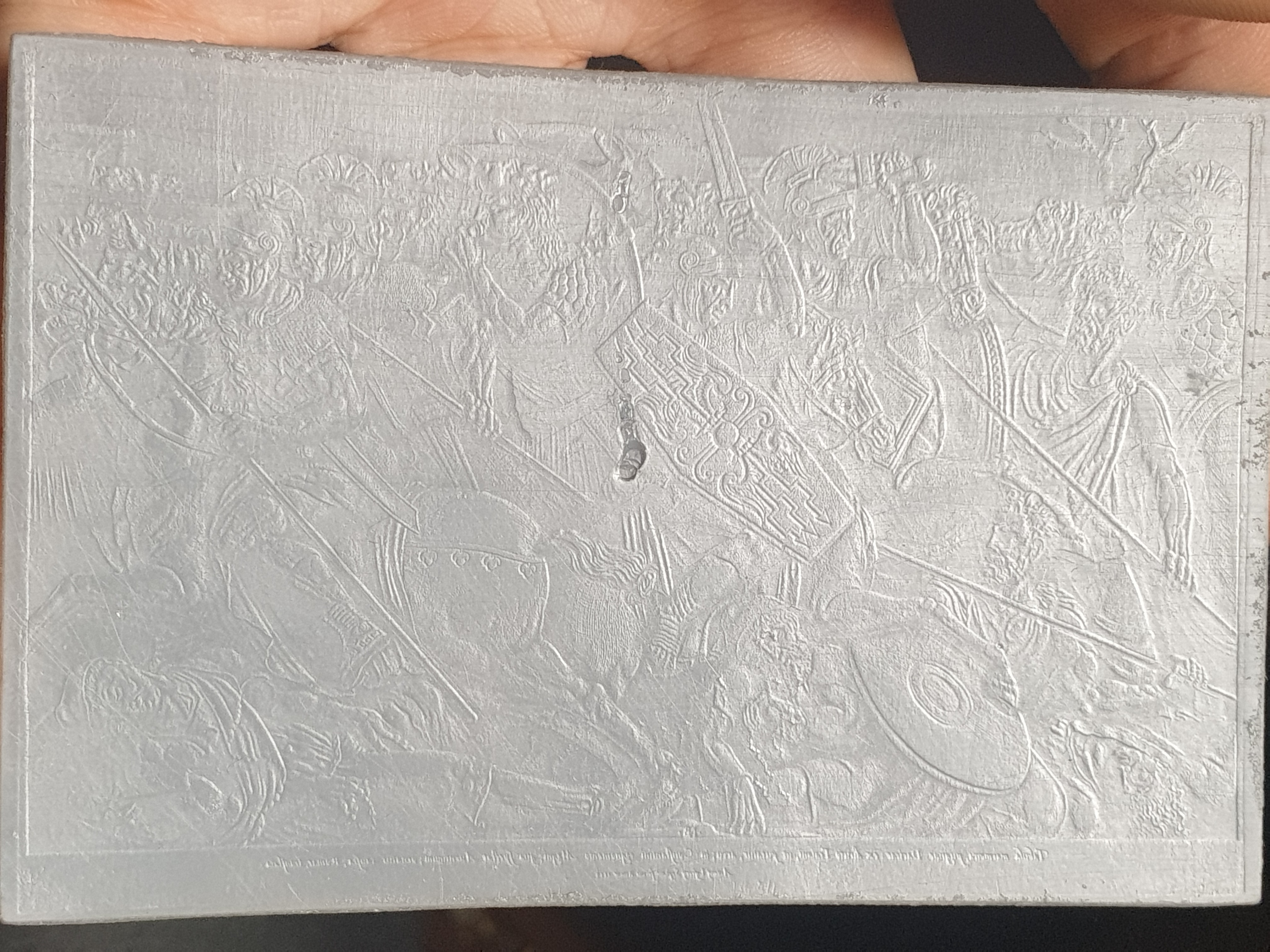
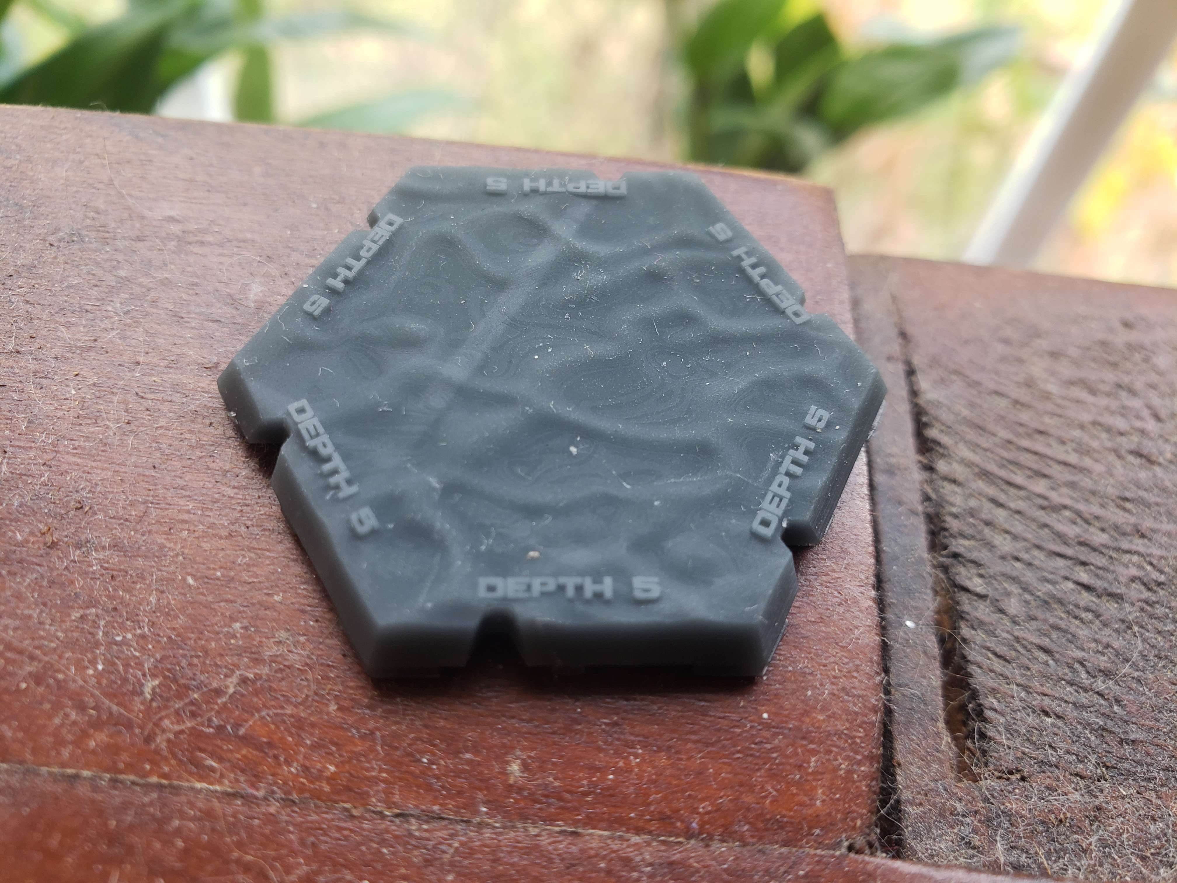
When I say overlapping layers I mean for each layer I sample a certian distiance for the gradient, I can just do the layer height but I find 3-4x that, resulting in wider overlapping gradients gets much smoother results, this can theoretically reduce detail but because the gradients are mapped from the surface they can actually bring out more detail, the only problem with this is it makes prints taller, but I have solved this by taking away a gradient from the downward facing faces, I haven’t tuned that fully but it’s amazing, because it can actually find details that no slicer can…

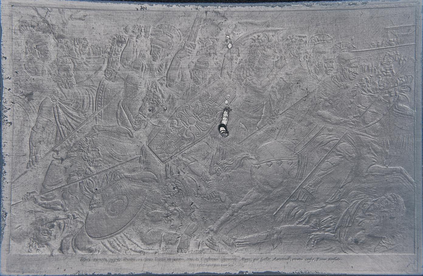
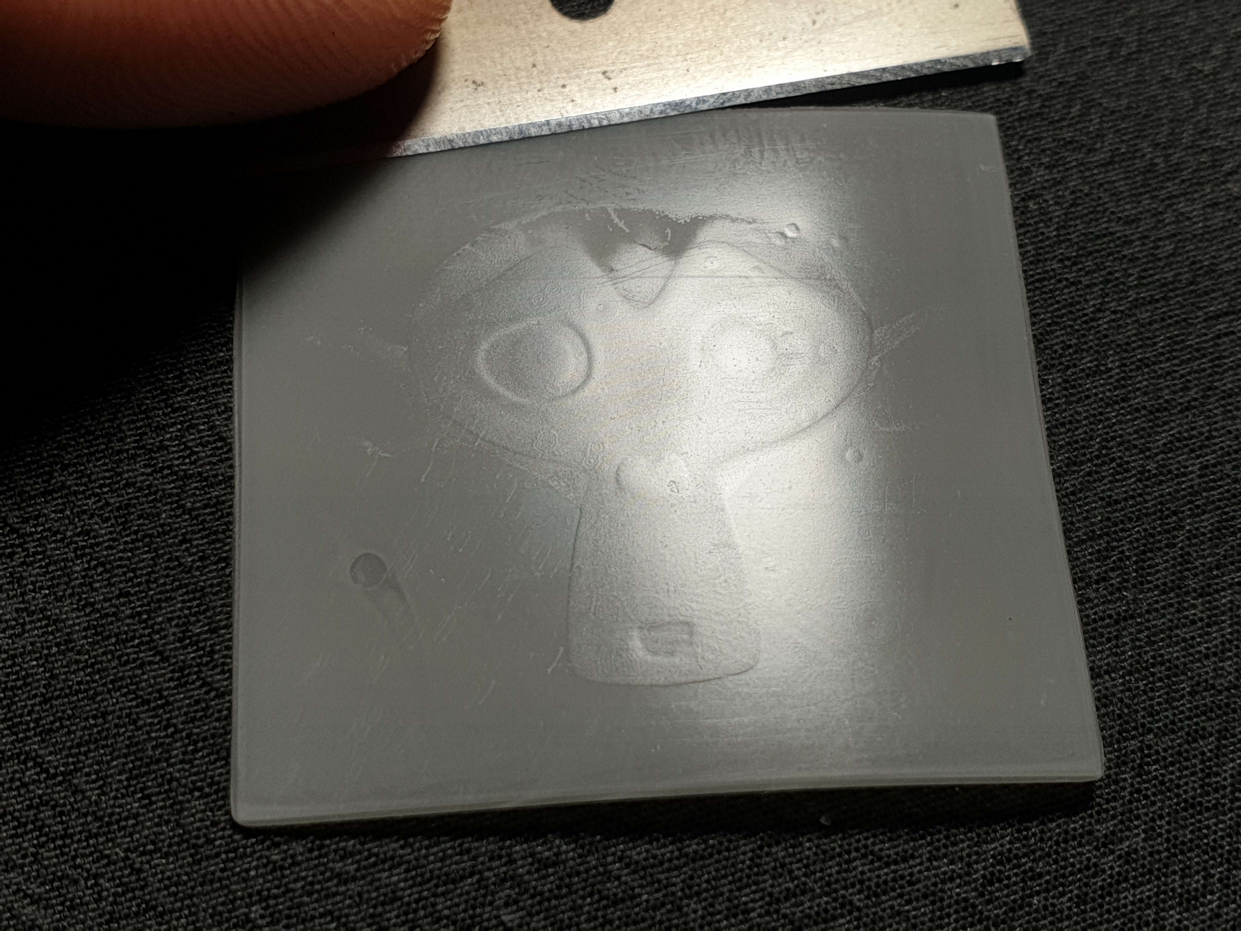
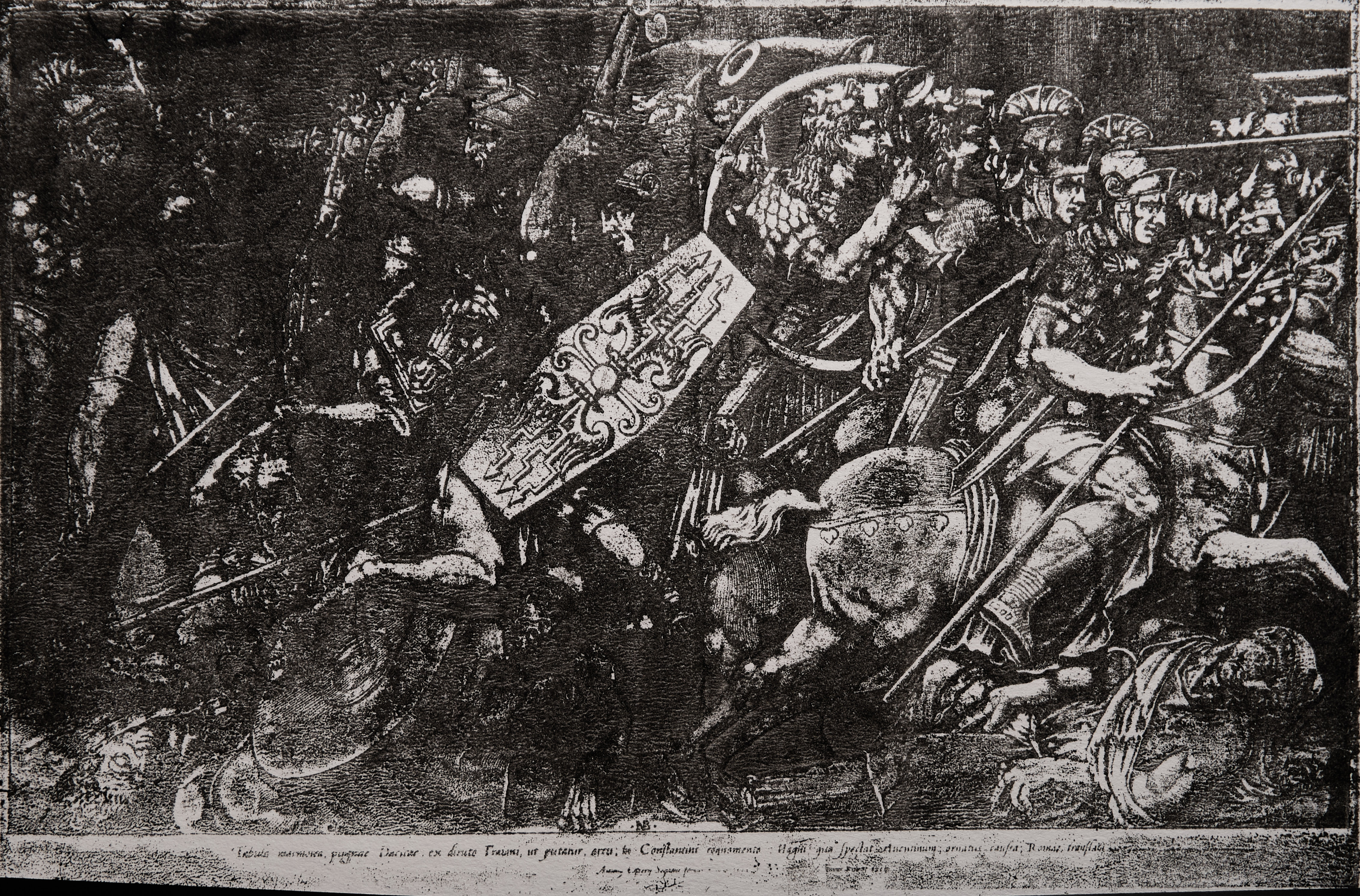
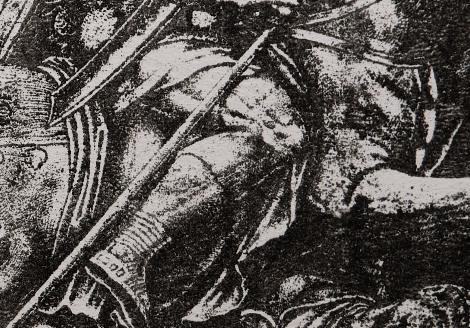
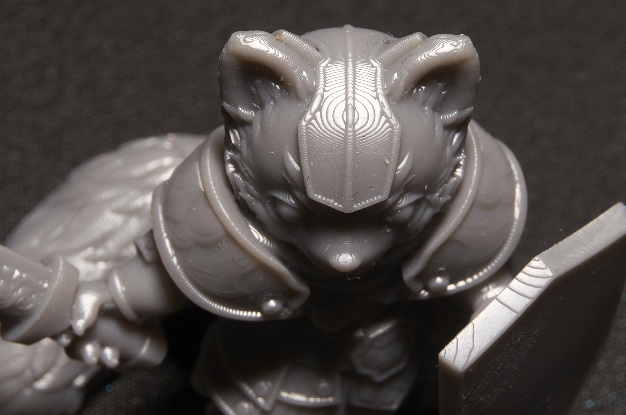
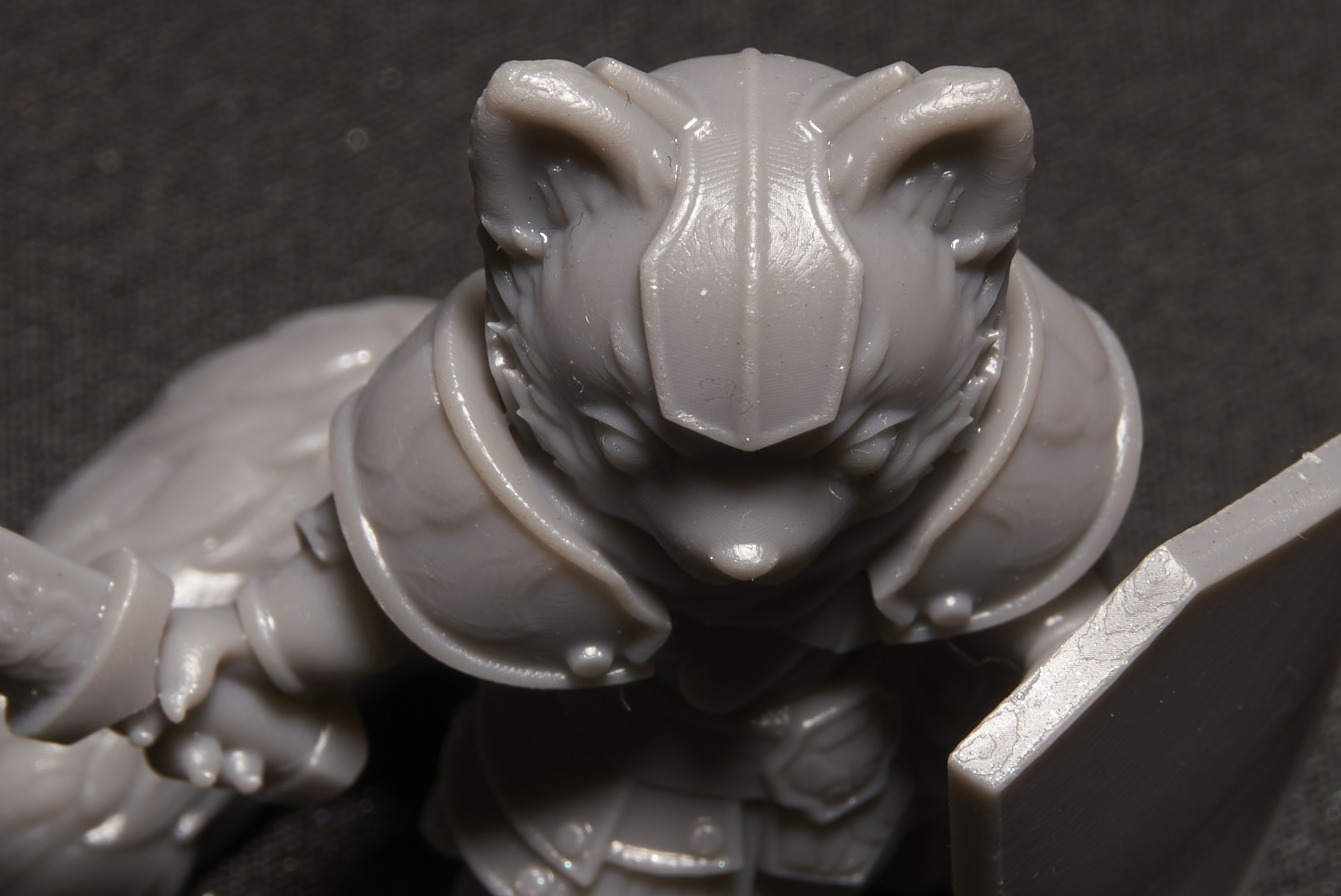
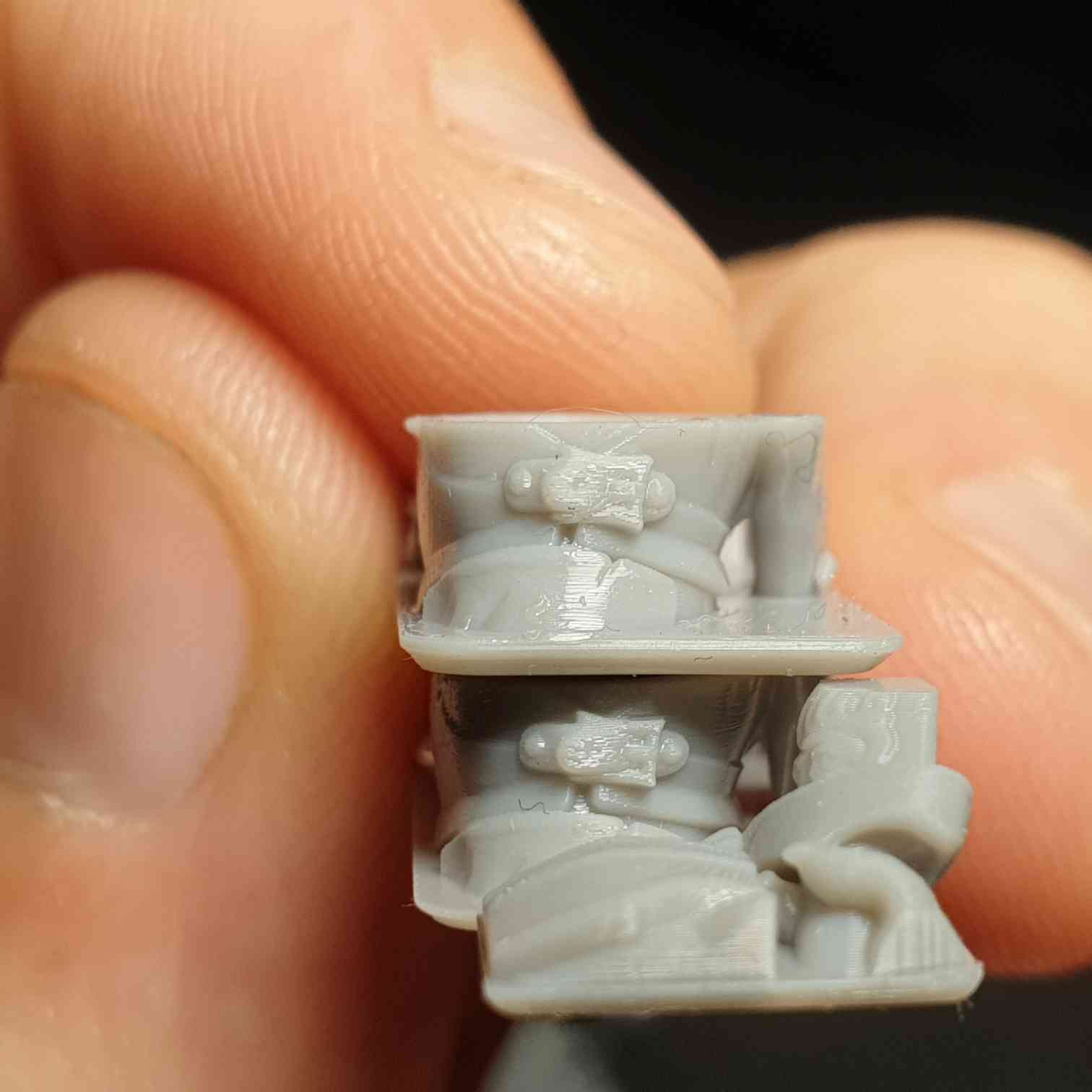
the left here is with the bottom side compensation, you can see at the left for example the trim around the coat is thicker on the z axis because it doesn’t have this compensation but it’s very thin on the left because the compensation is too strong.

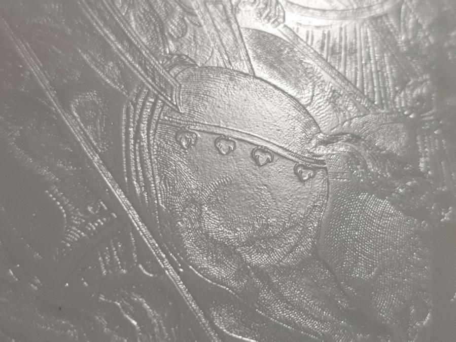
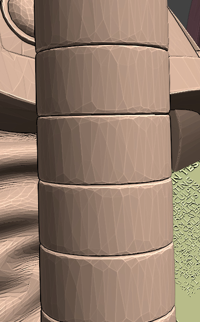
this is the staff model, the gaps between the rings are stupid small, as you can see it’s basically nothing yet the slicer was able to read them and in it’s overcompensation turn them into real gaps, if this was tuned better it could accurately make super thin vertical gaps.

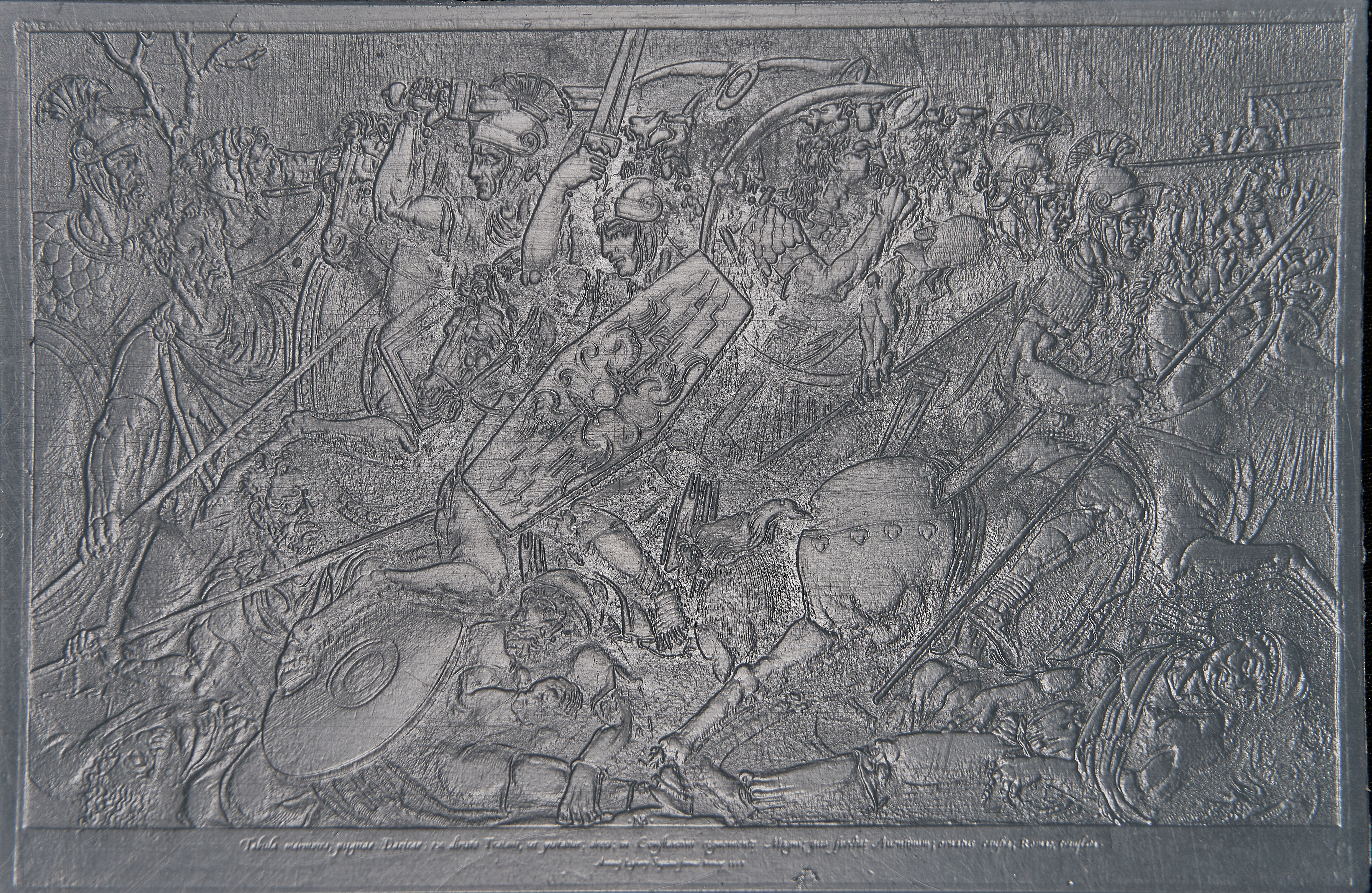
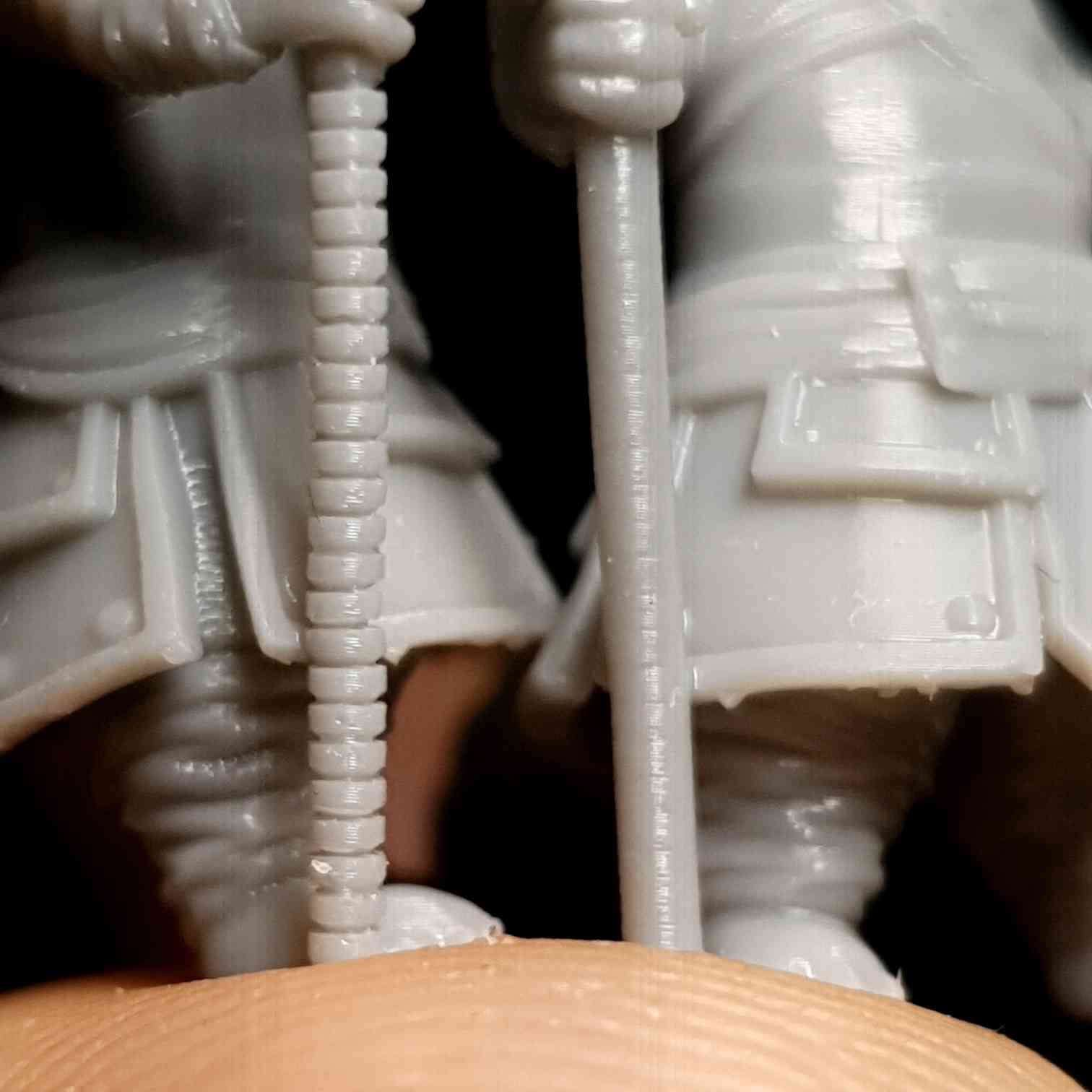
here is another example, top before compensation, bottom after, as you can see the top is vertically bloated.

What anycubic machines specifically do this XRP stuff? I assume it’s just the DLP? I can’t see a normal LCD printer doing that, eg there is one that uses the same screen as my saturn and now the m5 uses the same screen as the saturn 3

"So the Saturn 1 is an lcd printer right?

Did you do any other modifications?"

not really.

“How many pixels overlap do you have between gray shades among layers?”

As I said 3-4 layers works well, it’s not so much about pixels, but when the gradients get small it gets harder because it acts more like normal AA where the layers just change in XY width rather than making thin layers. also the size of the layer/shape varies how it cures or if it cures at low values because of bloom, if your printer like mine has lots of bloom then you actually rely on that in your exposure, if you do super thin things then due to lack of bloom it’s under exposed, thats why lcd printers can’t just print single pixel features like DLP.

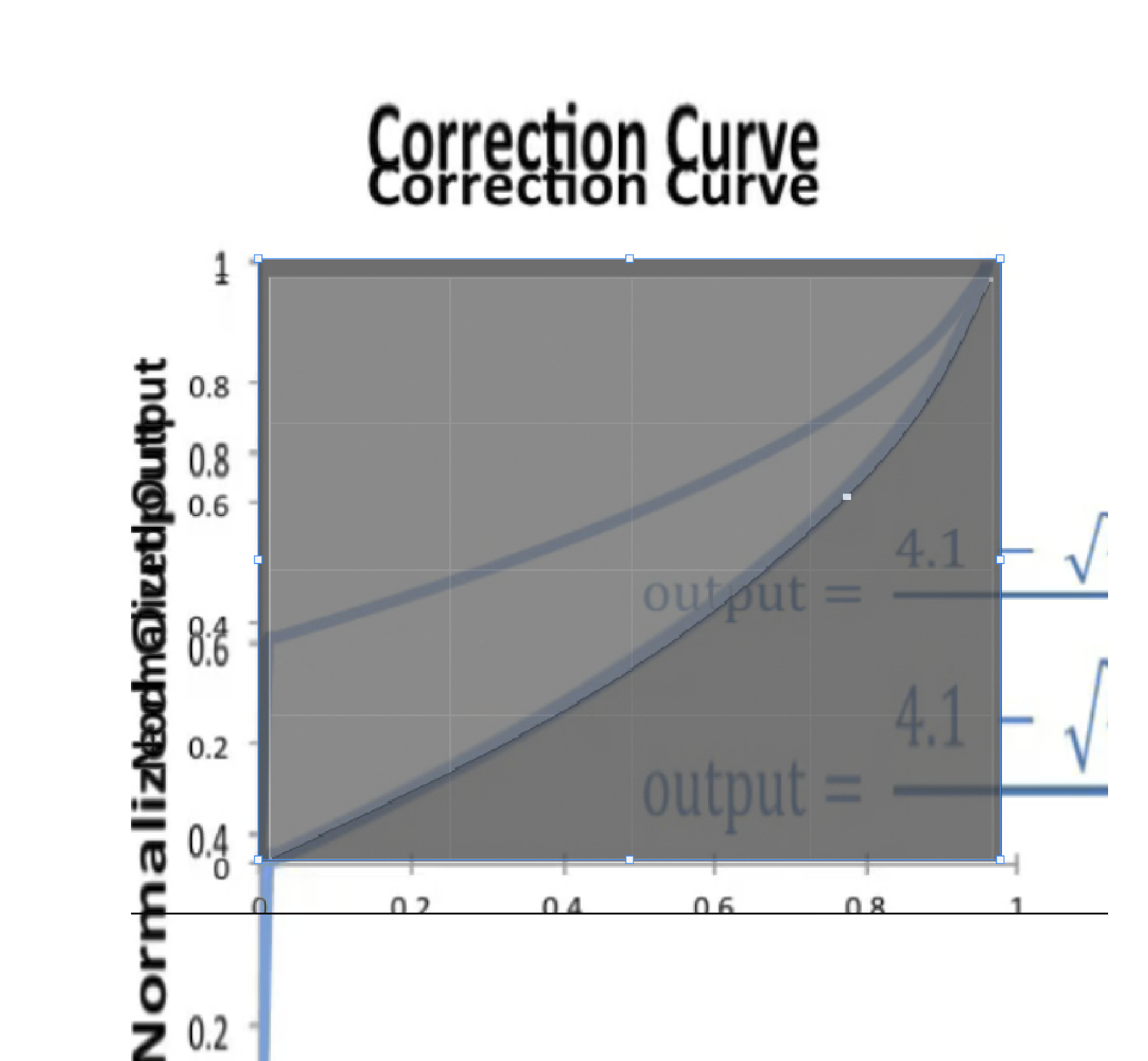
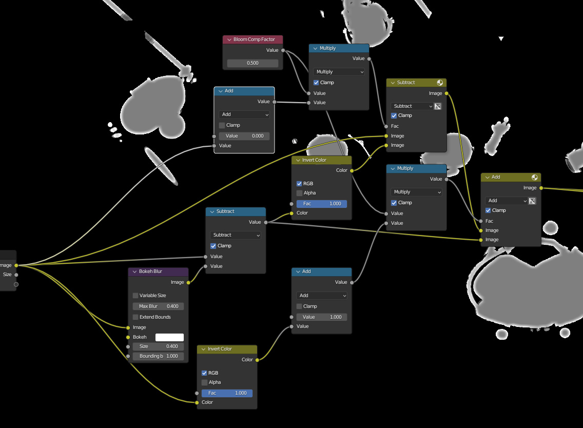
I’ve tried making some bloom compensation things like this


which should help with that, I think a perfect exposure is one where you expose so that you can expose a single pixel and then dim everything else to be dimensionally accurate, but as I touched on lower intensities can be an issue so there is a limit to how far that could go, at a certain point better hardware is needed, and new printers are far better than mine.

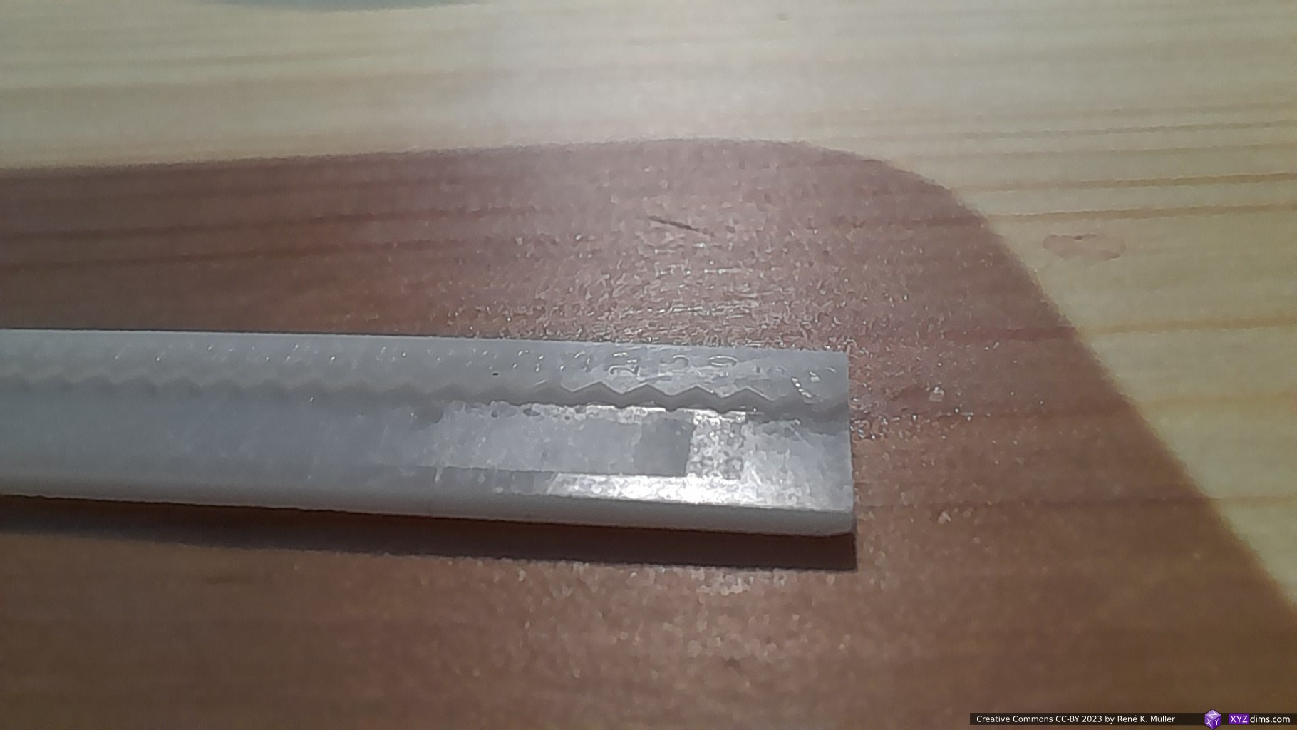
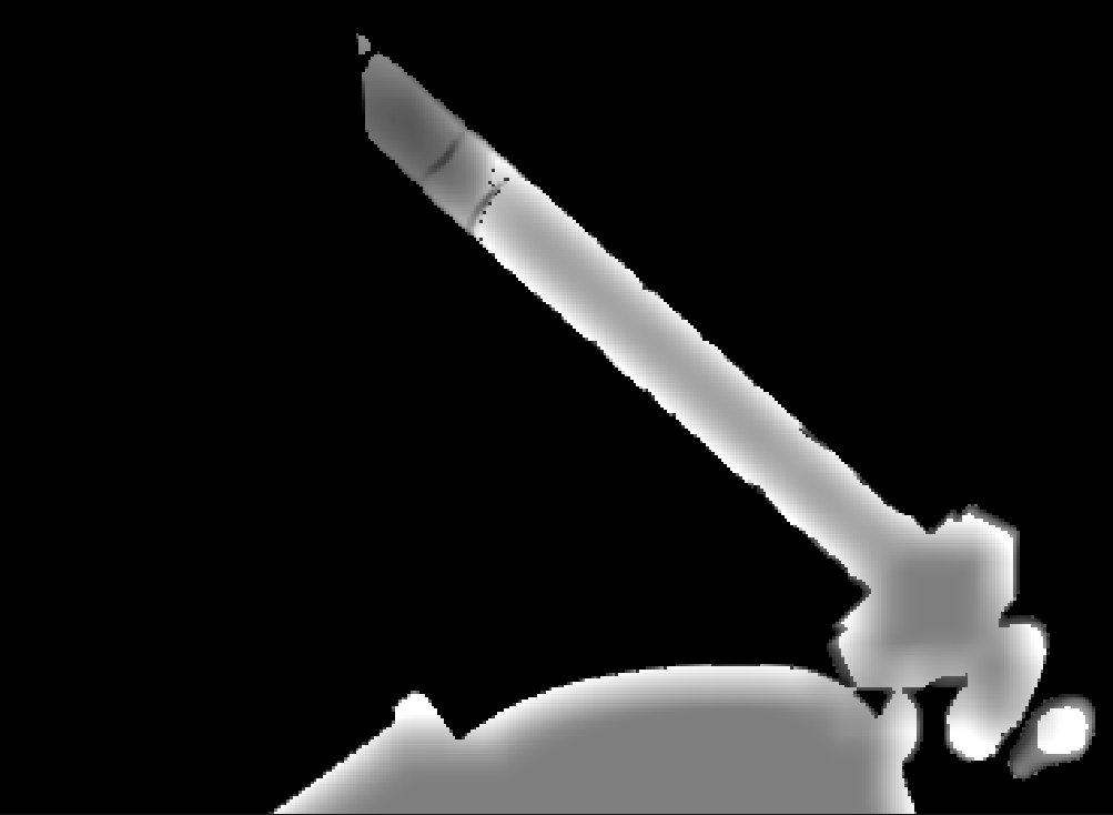
Back to printing small low intensity things, here is a test I made learning more about that and about how resin blooms<it’s not just overlapping light resin has a kind of surface tension, that’s why XYAA works even on DLP, I imagine it like welding where there is a hot area that you lead about by adding energy.

There is a lot here but relevant to this is just the fact that on consumer lcd printers, especially old ones like ine, bloom is king, without it things just don’t cure.

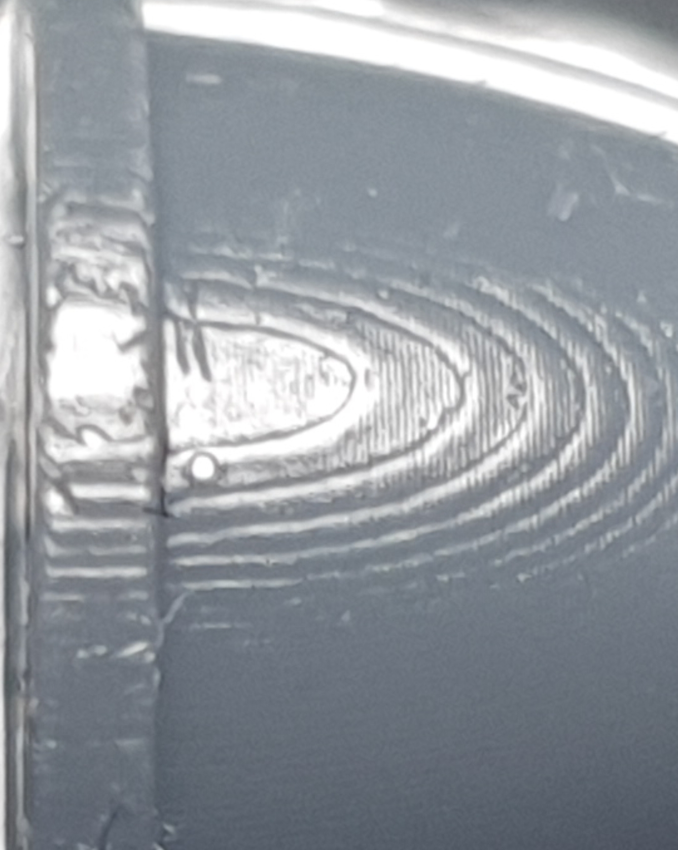
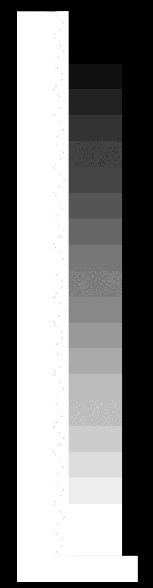
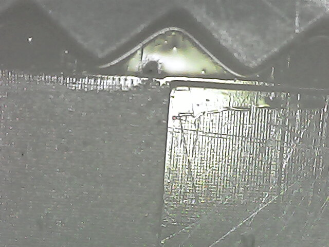
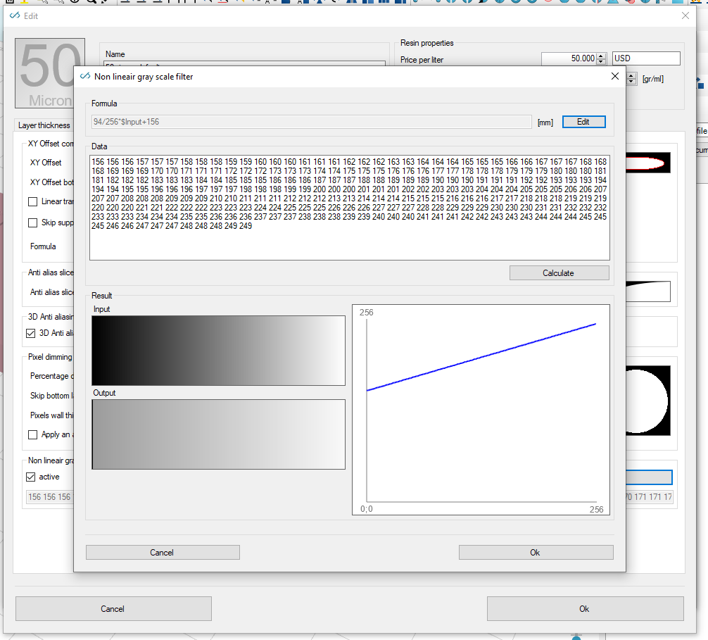
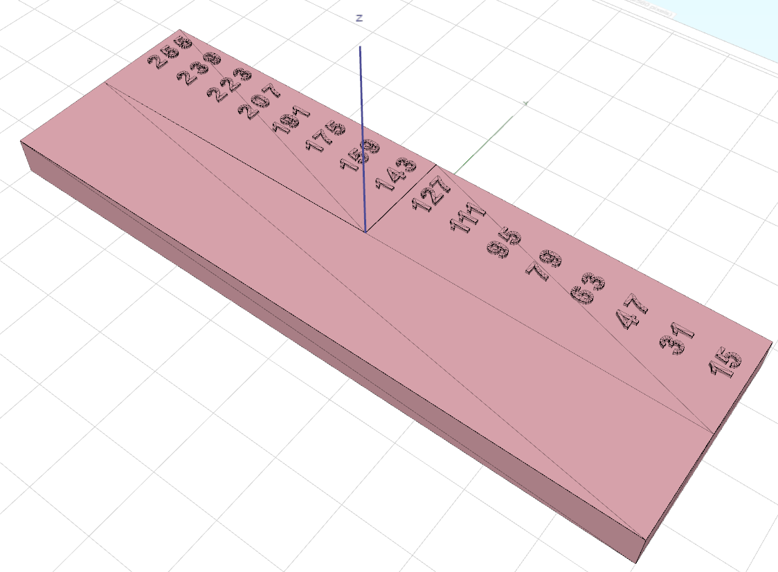
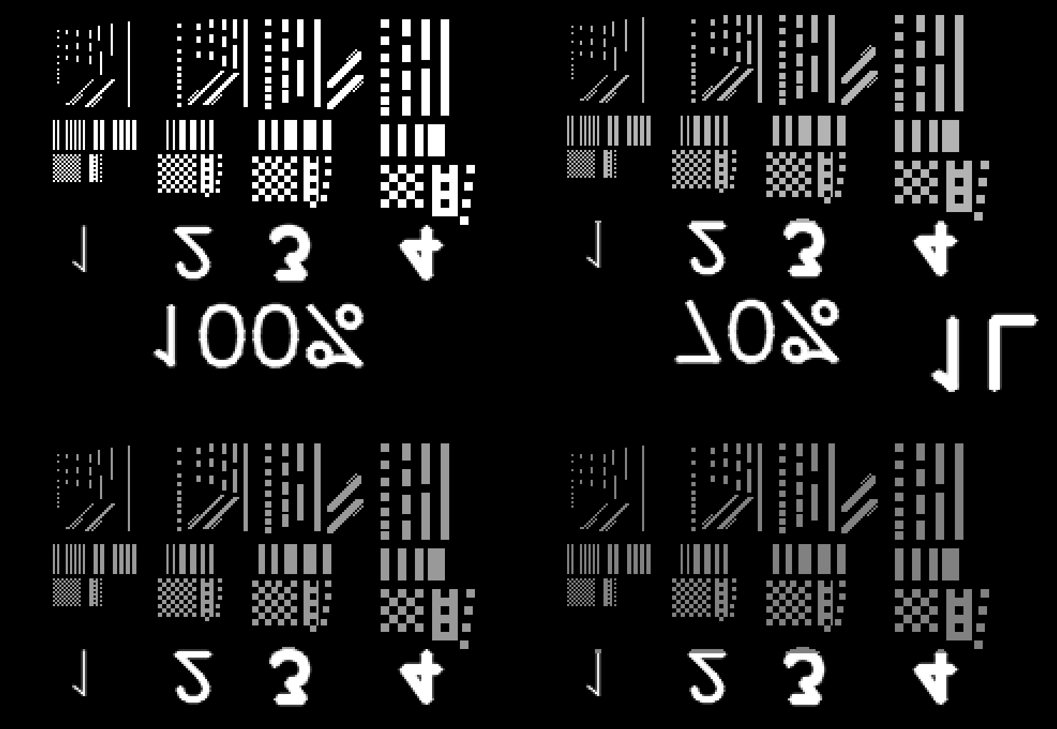
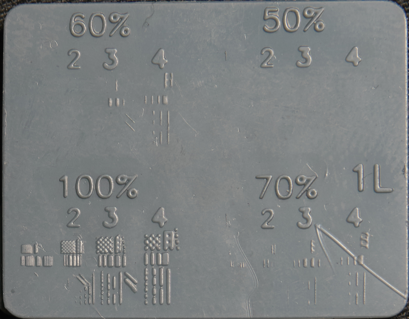
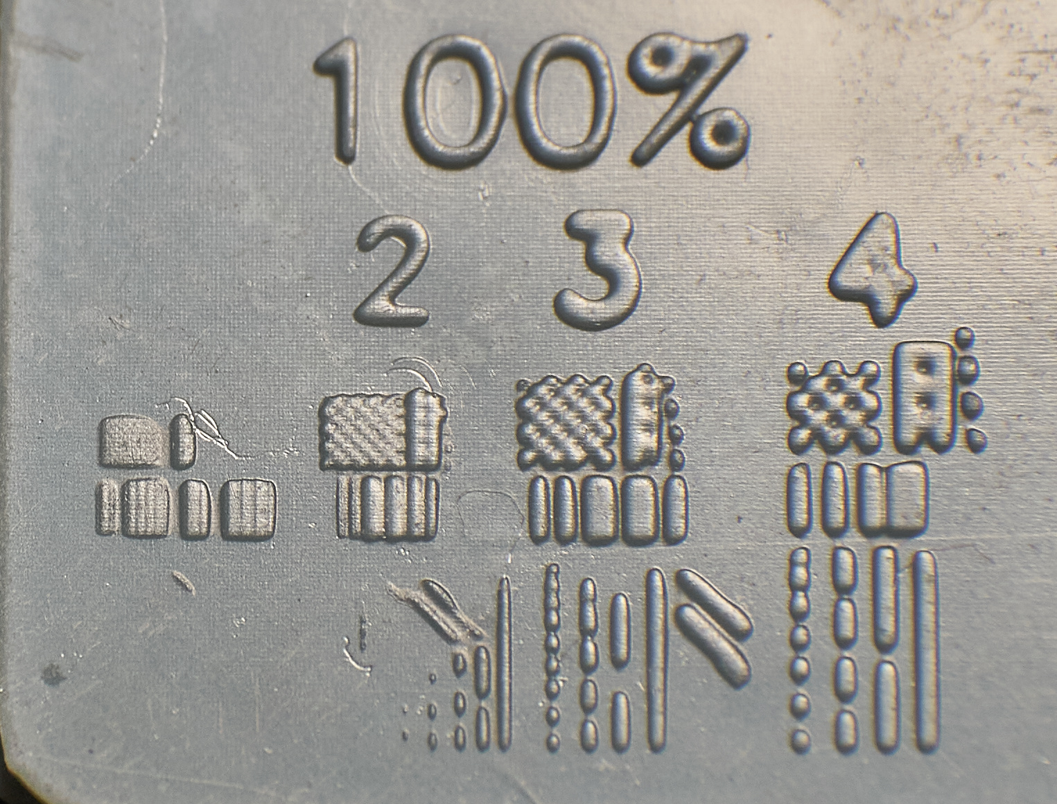
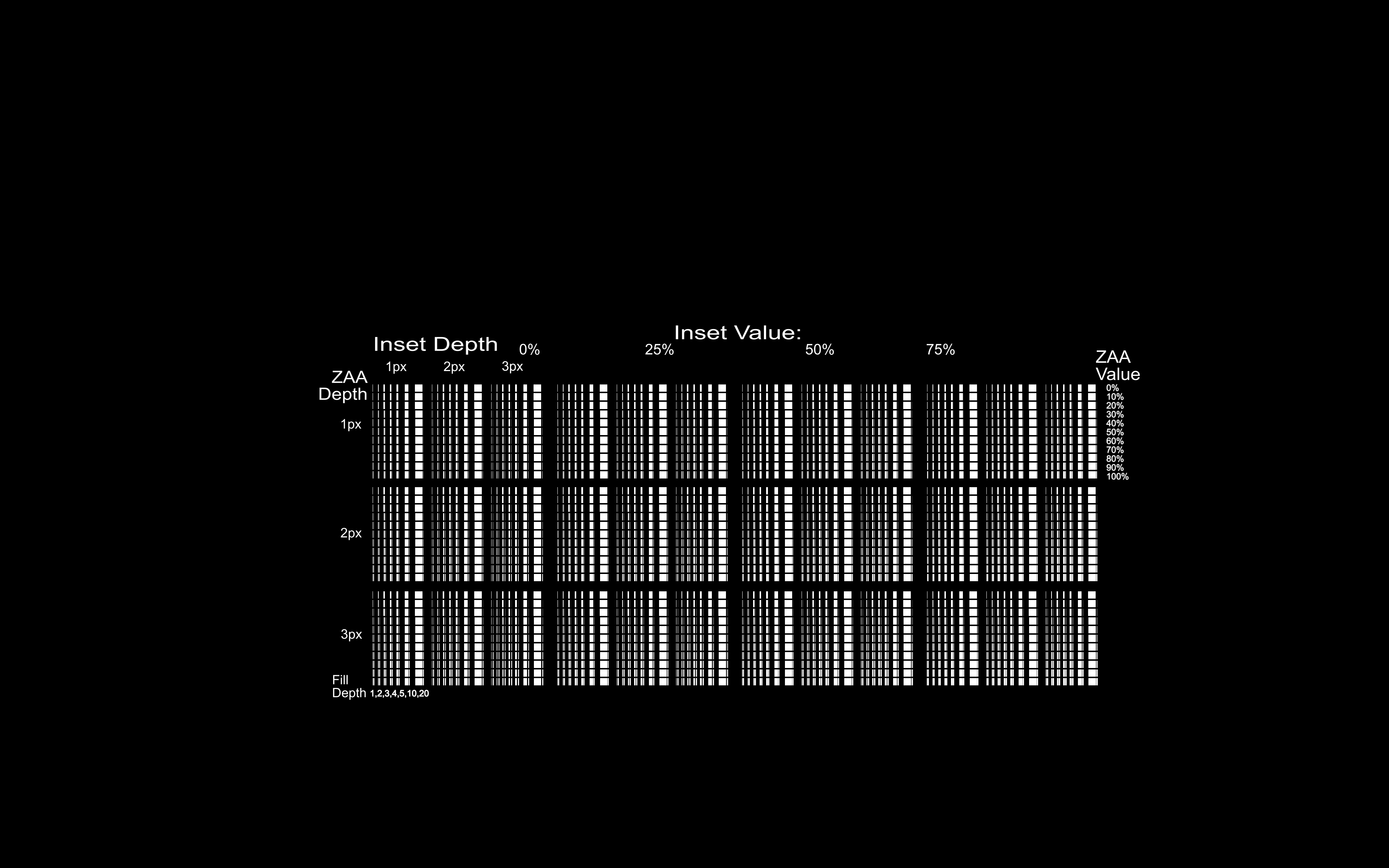
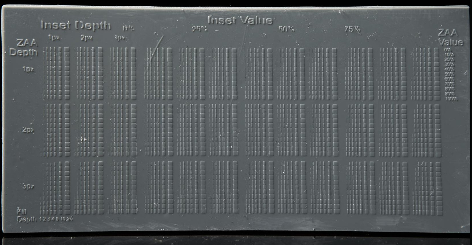
I then made a test with 2520 tests (this is a screenshot not the actual image)
to test how small I could get vertical gradients to form by using gaps to reduce bloom just enough


image

I did get some very thin 2px gradients with this but when I made the slicer do this it didn’t help, I haven’t tried very hard to get it to work so I might try again later but the thing is, while I really struggle to get pigmented resins to do VAA at less shallow angles in this video Dennys just magically got such angles smooth with normal chitu blur AA https://www.youtube.com/watch?v=cGAgyRVK32g&ab_channel=dennyswang

I need to get more info from him about this but I think it might have worked for him because he has a higher res printer with more parallel light than me, or perhaps it just worked because the high blur had no grey offset, and while grey offset is good for large layer perhaps its too much for steep layers / thin gradients because the high bloom from these layers which I tried to avoid with the techniques above could just be avoided with a lower grey offset, before the tests above I did try using a normal mask to dim the lower grey offset a bit to compensate for this but I didn’t take it down to no grey offset, I just made it slightly darker so perhaps I will try again at some point with a bigger dip.

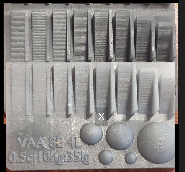
Also back to how I’m overlapping layers, it’s kind of cheating, it would be ideal to do VAA without it but it helps so much, eg with 4x overlapping layers thin gradients are 4x wider, and it doesn’t matter if the grey offset isn’t perfect because too high and well the lowest value is being projected at an area 3 layer heights away so it won’t cure anyway and too low and well, again well that layer will still overlap the previous ones good enough. (when my tests say 4L or 1L that’s the layer overlap) Now while it’s more forgiving it can still be a problem, you don’t want to have the exposure too low when doing this because then it can cause flaky partially cured layers

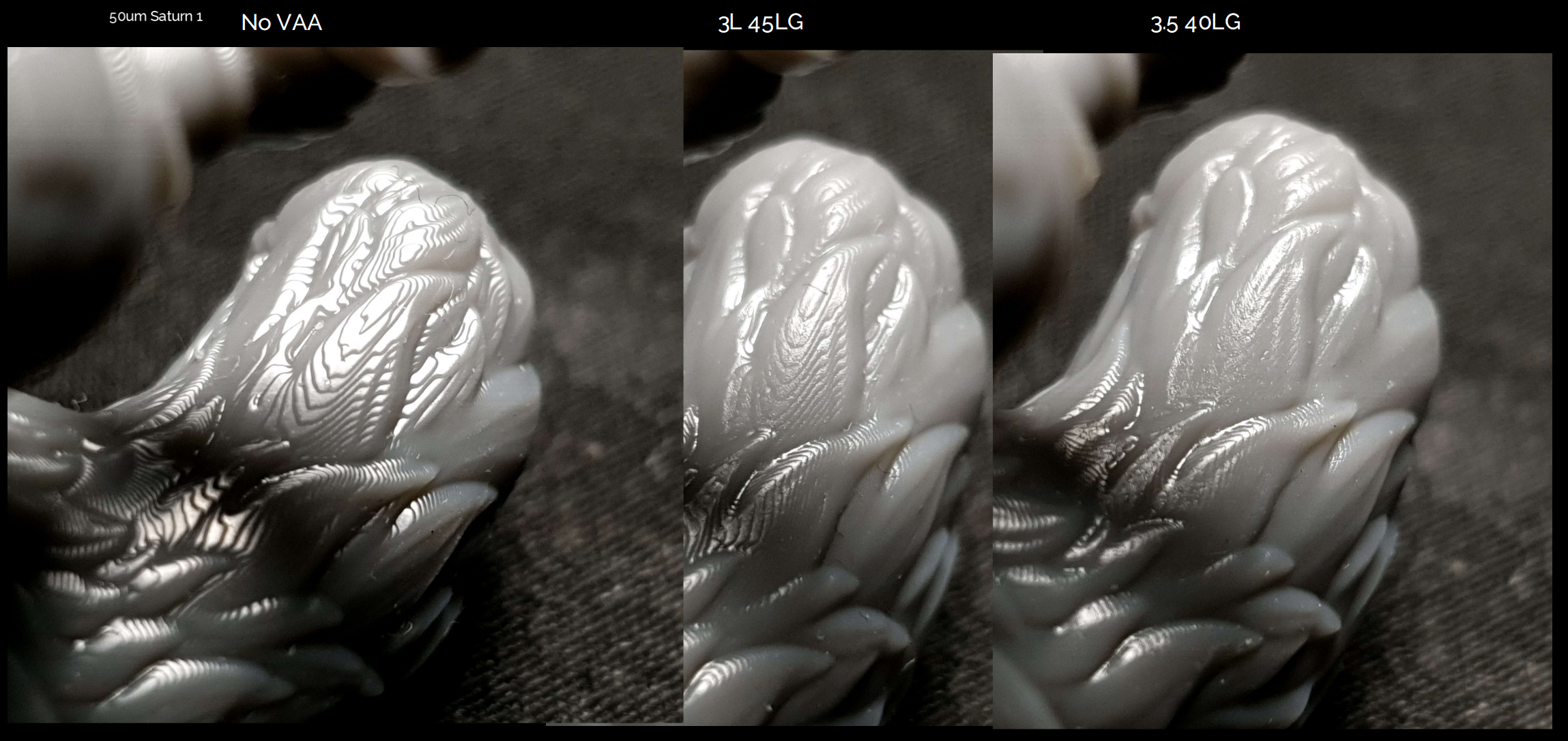
eg here overlapping layers with too low grey offset vs no VAA
(and above I posed good grey offset with overlapping VAA layers on this model)

I posted this image before, this is with 1L to show how lower grey offset affects that, too low and you don’t cover the previous layer too high and there is still a layer edge which is more visible than it needs to be. so it’s very hard to get this perfect, without perfect bloom compensation it’s actually impossible because the correct grey offset won’t be the same on a large gradient vs a thin one vs a long thin one etc. and back to the Dennys findings, he just used blur from chitu, that blur will make a small overlapping gradient on every layer until the gradient gets so shallow that they don’t overlap, that’s where my slicer does better, so if even that overlaps, why not overlap VAA? I get that 4L might not be perfectly accurate, and this is where my techniques differe from the ember team, I want visual quality so it doesn’t need to be technically perfect as 1L is, however, if you want that 1L technical accuracy then you should still overlap by a small amount, my slicer can do any overlap, eg I can just type in 1.1 or 1.5L for an object and it will work. Also if you only have 4 bit anycubics with a usable range of like 7 steps then getting the perfect grey offset will be harder. Do you not have any other printers?

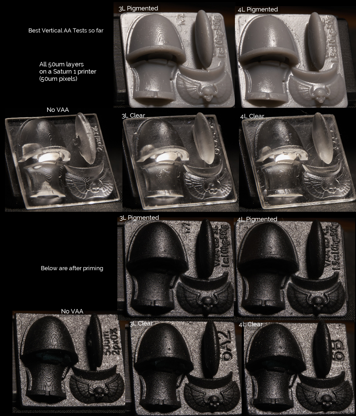
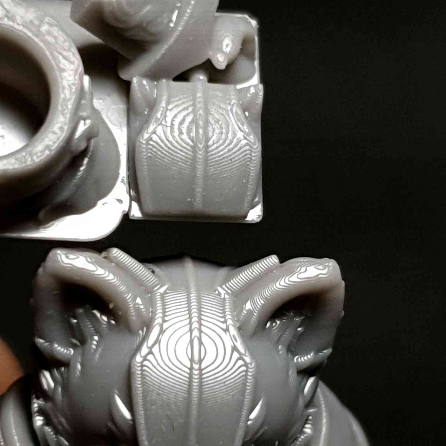
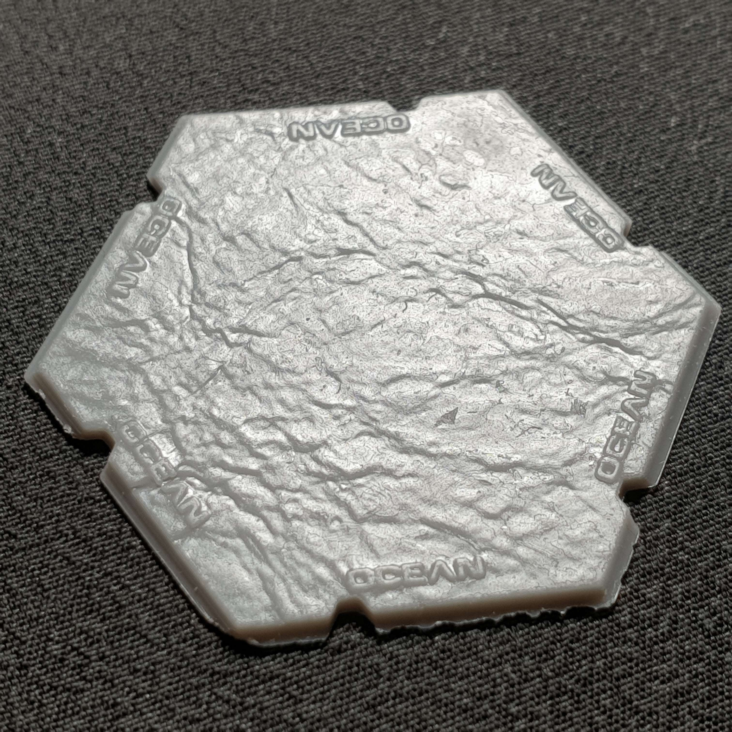
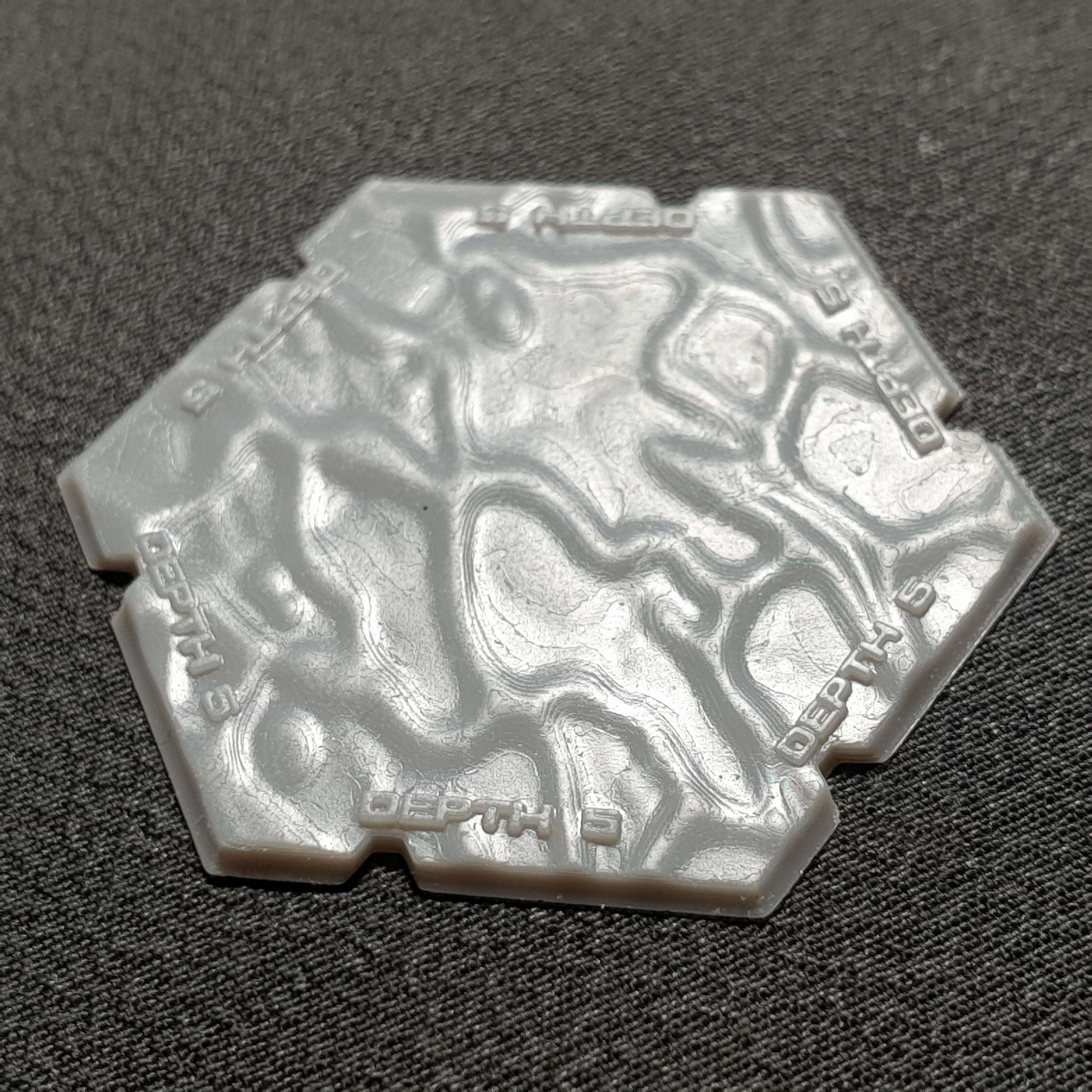
also here is a file I sliced for a friend with an anycubic printer, unfortunately there isn’t a non vaa one besides to compare but I have a pic from someone else who printed the same thing without VAA

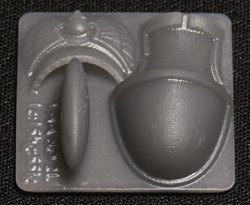
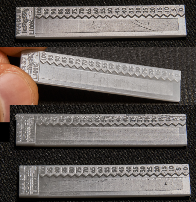
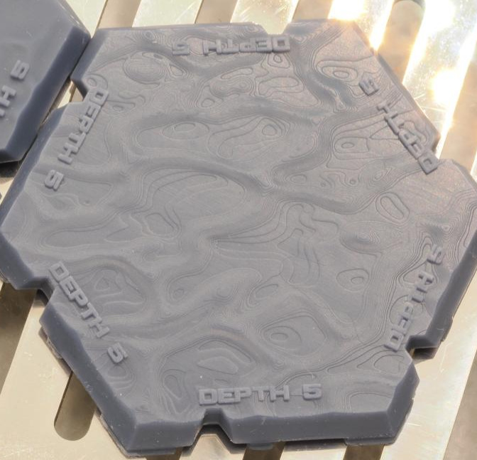
here are some of my prints of these bases


#44

Hi Tom,

Thanks for your detailed answer. I don’t understand 100% of what you write to be honest but most of it.
I think that it having a to sharp cut at the lower end makes sense that the resin is to opaque. I’ve ordered transparent resins to make a good test to confirm that.

I’ve watched the youtube movie you mention but to me it doesnt’ seem he solve the issue that we are looking at here, very shallow angles. Basically in the image below at the left side you still see stairs. And this is 0-20 degrees. It’s just hard to see on youtube. Every sphere he shows he looks at the side… not the top.

Then i’ve read the chitubox article again on anti aliasing and their grey level and blur system. Reading it now for the 3rd time but still not clear to me what they are trying to explain. Or how their blur system works.

The last sentence writes that the order of operation is: “blur -> gray level -> anti aliasing”.
If that is the case, then the anti aliasing if done without any information of the geometry; as that is blurred away in the previous steps
When I look at their blur algoritm it seems to me as if it’s just a linear softening; not even gaussian. But perhaps lineair makes more sense as otherwise it might go to fast to black.

My question to you about overlap was not how many layers, but how many pixels sideways?
Our slice core works by accurately outputting the pixel gray levels by calculating exactly how much of the voxel space is covered by the model in 3d. So there is currently no overlay between layers (see 2 top layers of a sphere below)… that’s why i was wondering if you make your top layer in this example even larger?

image