True 3D Antialiasing


#42

Hi Tom,

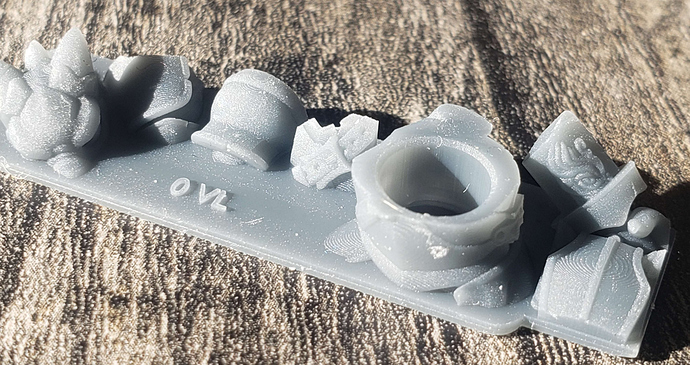
Thx. I tried a sphere as a last example last friday. I noticed layerlines at the lower boundary… so probably with 50 micron layers that would mean still a step of 25-30 micron left.
I think below that level there is just no exposure at the build table. My theory would be the pigment just prevents it.
I’ve ordered 3 more different resins, amongst others a clear one.

Anycubic is 4bit, we discussed it and we think it’s because of the DMD system it uses. It has a native 720p resolution, but it does something called XRP, which is basically shifint the optical system so it increases resolution 4 times. But this probably means they took a shortcut (or necessity) in the datapath. So intest of 8 bit they ended up with 4 bit per pixel. We didn’t reason long enough but it could also be because there is otherwise no mathematical solution as you are basically overlaying pixels… anyhow. Check here if you want to see how this works under the hood: https://www.optotune.com/pixel-shifting

So the Saturn 1 is an lcd printer right?

Did you do any other modifications?

I read somewhere in the beginning that you said ‘overlapping’ layers?
How many pixels overlap do you have between gray shades among layers?
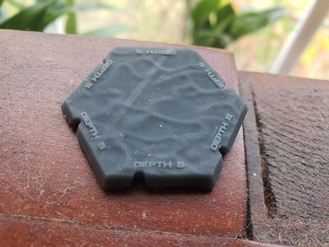
When I’m back in office i’ll post some detail pics of the top of my sphere; i’m curious how yours looks, perhaps the true 3d anti aliased shape coming from our slice core is just not aliased enough yet…

Elco


#43

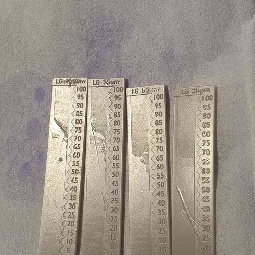
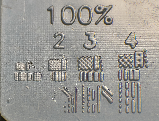
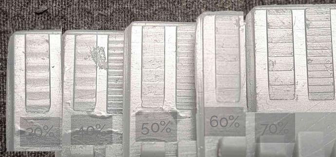
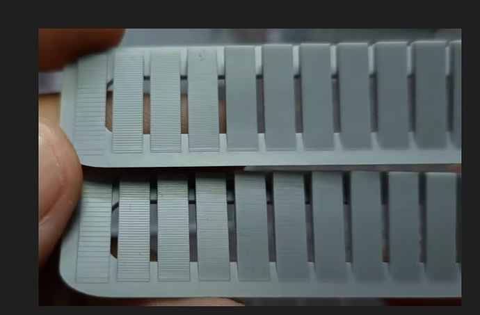
Here is a group of different linear gradient tests I did recently, I actually set up a .ctb4 file so that it did all these different layer heights on one print by printing at 50um and then getting to a certain point and lifting 25um to do the 25um gradient but blank on the other ones, then lifting another 25um to do the 50um etc. As you can see 25um with my saturn 1 was silky smooth, the last layer on that isn’t 25-30micron, it’s stupid small, however as the layer height gets higher the end gets more abrupt as the resin starts to cure from the fep up rather than plate down. Interestingly even at 100um ar like 85 there was some area where it did cure from the previous layer down, not fep first, but not for the lower intensities. However from the fact that there was even a tiny bit like that it shows that with 80+ intensity I can actually print previous layer down on my printer at 100um, the problem is that with a normal layer exposure time that intensity almost builds a full 50um layer thickness, but because we can see it did start from the previous layer at that intensity, it means the same intensity but shorter times would actually yield a thin layer at 50um. I thought that more direct light would cure plate down at thicker layer better, and while I can’t test that because I don’t have a more direct light printer, from this it’s clear that better results at thicker layers can be achieved by using a far higher intensity printer or by an idea I’ve had which I call semi continuous printing, I can’t remember if I explained this fully here, again I have a thread on discord about this, but basically the idea is to go to a certain layer height eg 50um and then cure a few very thin partial layers to build up one layer. I’ve done some tests with this and it worked but not consistently, at the time I couldn’t do 0 lift, anything under 10um would default to a normal lift height which makes multi exposures a pain, but I discovered in the G code I can just change M8070 to z0 and then 0 lift heights work so I will have to do more testing for this stuff at some point.

So yeha you might have abrupt issues because the layer height is too high. You also may have them because your lower grey offset is too high, I found lowering it 10-15% from the linear gradient lowest value was a good spot. And yeha the 4 bit of the anycubics will also limit you because if you are only using half the values thats like 7 values which is not much.

When I say overlapping layers I mean for each layer I sample a certian distiance for the gradient, I can just do the layer height but I find 3-4x that, resulting in wider overlapping gradients gets much smoother results, this can theoretically reduce detail but because the gradients are mapped from the surface they can actually bring out more detail, the only problem with this is it makes prints taller, but I have solved this by taking away a gradient from the downward facing faces, I haven’t tuned that fully but it’s amazing, because it can actually find details that no slicer can…

the left here is with the bottom side compensation, you can see at the left for example the trim around the coat is thicker on the z axis because it doesn’t have this compensation but it’s very thin on the left because the compensation is too strong.

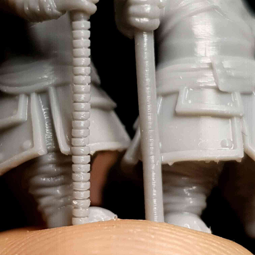
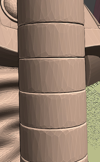
this is the staff model, the gaps between the rings are stupid small, as you can see it’s basically nothing yet the slicer was able to read them and in it’s overcompensation turn them into real gaps, if this was tuned better it could accurately make super thin vertical gaps.

here is another example, top before compensation, bottom after, as you can see the top is vertically bloated.

What anycubic machines specifically do this XRP stuff? I assume it’s just the DLP? I can’t see a normal LCD printer doing that, eg there is one that uses the same screen as my saturn and now the m5 uses the same screen as the saturn 3

"So the Saturn 1 is an lcd printer right?

Did you do any other modifications?"

not really.

“How many pixels overlap do you have between gray shades among layers?”

As I said 3-4 layers works well, it’s not so much about pixels, but when the gradients get small it gets harder because it acts more like normal AA where the layers just change in XY width rather than making thin layers. also the size of the layer/shape varies how it cures or if it cures at low values because of bloom, if your printer like mine has lots of bloom then you actually rely on that in your exposure, if you do super thin things then due to lack of bloom it’s under exposed, thats why lcd printers can’t just print single pixel features like DLP.

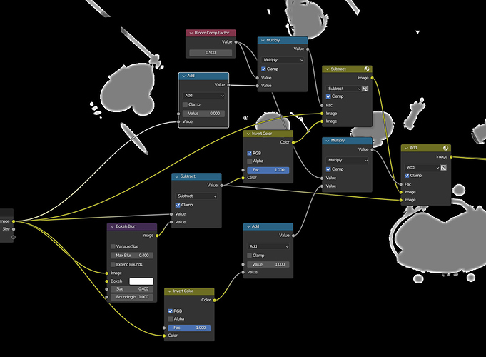
I’ve tried making some bloom compensation things like this


which should help with that, I think a perfect exposure is one where you expose so that you can expose a single pixel and then dim everything else to be dimensionally accurate, but as I touched on lower intensities can be an issue so there is a limit to how far that could go, at a certain point better hardware is needed, and new printers are far better than mine.

Back to printing small low intensity things, here is a test I made learning more about that and about how resin blooms<it’s not just overlapping light resin has a kind of surface tension, that’s why XYAA works even on DLP, I imagine it like welding where there is a hot area that you lead about by adding energy.

There is a lot here but relevant to this is just the fact that on consumer lcd printers, especially old ones like ine, bloom is king, without it things just don’t cure.

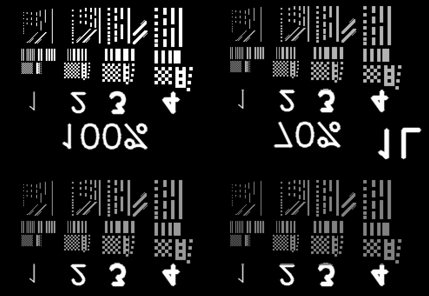
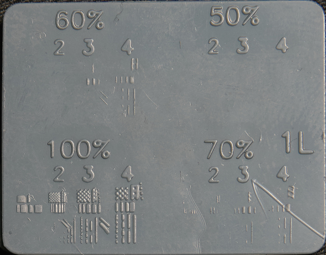
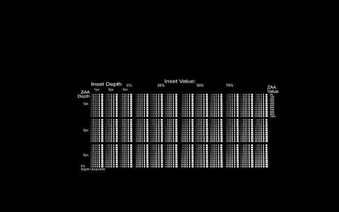
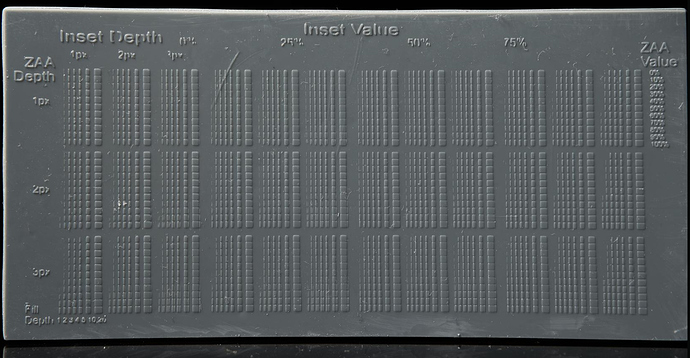
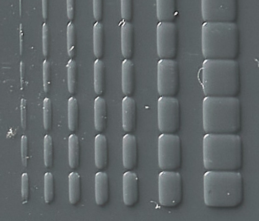
I then made a test with 2520 tests (this is a screenshot not the actual image)
to test how small I could get vertical gradients to form by using gaps to reduce bloom just enough

image

I did get some very thin 2px gradients with this but when I made the slicer do this it didn’t help, I haven’t tried very hard to get it to work so I might try again later but the thing is, while I really struggle to get pigmented resins to do VAA at less shallow angles in this video Dennys just magically got such angles smooth with normal chitu blur AA https://www.youtube.com/watch?v=cGAgyRVK32g&ab_channel=dennyswang

I need to get more info from him about this but I think it might have worked for him because he has a higher res printer with more parallel light than me, or perhaps it just worked because the high blur had no grey offset, and while grey offset is good for large layer perhaps its too much for steep layers / thin gradients because the high bloom from these layers which I tried to avoid with the techniques above could just be avoided with a lower grey offset, before the tests above I did try using a normal mask to dim the lower grey offset a bit to compensate for this but I didn’t take it down to no grey offset, I just made it slightly darker so perhaps I will try again at some point with a bigger dip.

Also back to how I’m overlapping layers, it’s kind of cheating, it would be ideal to do VAA without it but it helps so much, eg with 4x overlapping layers thin gradients are 4x wider, and it doesn’t matter if the grey offset isn’t perfect because too high and well the lowest value is being projected at an area 3 layer heights away so it won’t cure anyway and too low and well, again well that layer will still overlap the previous ones good enough. (when my tests say 4L or 1L that’s the layer overlap) Now while it’s more forgiving it can still be a problem, you don’t want to have the exposure too low when doing this because then it can cause flaky partially cured layers

eg here overlapping layers with too low grey offset vs no VAA
(and above I posed good grey offset with overlapping VAA layers on this model)

I posted this image before, this is with 1L to show how lower grey offset affects that, too low and you don’t cover the previous layer too high and there is still a layer edge which is more visible than it needs to be. so it’s very hard to get this perfect, without perfect bloom compensation it’s actually impossible because the correct grey offset won’t be the same on a large gradient vs a thin one vs a long thin one etc. and back to the Dennys findings, he just used blur from chitu, that blur will make a small overlapping gradient on every layer until the gradient gets so shallow that they don’t overlap, that’s where my slicer does better, so if even that overlaps, why not overlap VAA? I get that 4L might not be perfectly accurate, and this is where my techniques differe from the ember team, I want visual quality so it doesn’t need to be technically perfect as 1L is, however, if you want that 1L technical accuracy then you should still overlap by a small amount, my slicer can do any overlap, eg I can just type in 1.1 or 1.5L for an object and it will work. Also if you only have 4 bit anycubics with a usable range of like 7 steps then getting the perfect grey offset will be harder. Do you not have any other printers?

also here is a file I sliced for a friend with an anycubic printer, unfortunately there isn’t a non vaa one besides to compare but I have a pic from someone else who printed the same thing without VAA

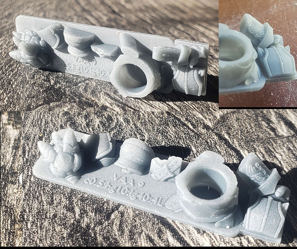
here are some of my prints of these bases


#44

Hi Tom,

Thanks for your detailed answer. I don’t understand 100% of what you write to be honest but most of it.
I think that it having a to sharp cut at the lower end makes sense that the resin is to opaque. I’ve ordered transparent resins to make a good test to confirm that.

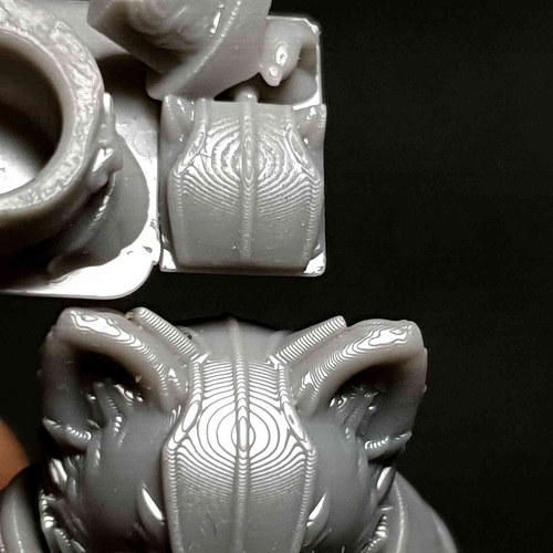
I’ve watched the youtube movie you mention but to me it doesnt’ seem he solve the issue that we are looking at here, very shallow angles. Basically in the image below at the left side you still see stairs. And this is 0-20 degrees. It’s just hard to see on youtube. Every sphere he shows he looks at the side… not the top.

Then i’ve read the chitubox article again on anti aliasing and their grey level and blur system. Reading it now for the 3rd time but still not clear to me what they are trying to explain. Or how their blur system works.

The last sentence writes that the order of operation is: “blur -> gray level -> anti aliasing”.
If that is the case, then the anti aliasing if done without any information of the geometry; as that is blurred away in the previous steps
When I look at their blur algoritm it seems to me as if it’s just a linear softening; not even gaussian. But perhaps lineair makes more sense as otherwise it might go to fast to black.

My question to you about overlap was not how many layers, but how many pixels sideways?
Our slice core works by accurately outputting the pixel gray levels by calculating exactly how much of the voxel space is covered by the model in 3d. So there is currently no overlay between layers (see 2 top layers of a sphere below)… that’s why i was wondering if you make your top layer in this example even larger?

image


#45

Aah that’s funny. I ran some tests on chitubox. It seems their ‘gray level’ is already a non-lineair filter of what we are trying to accomplish here. Just their explanations in software/website make no sense.
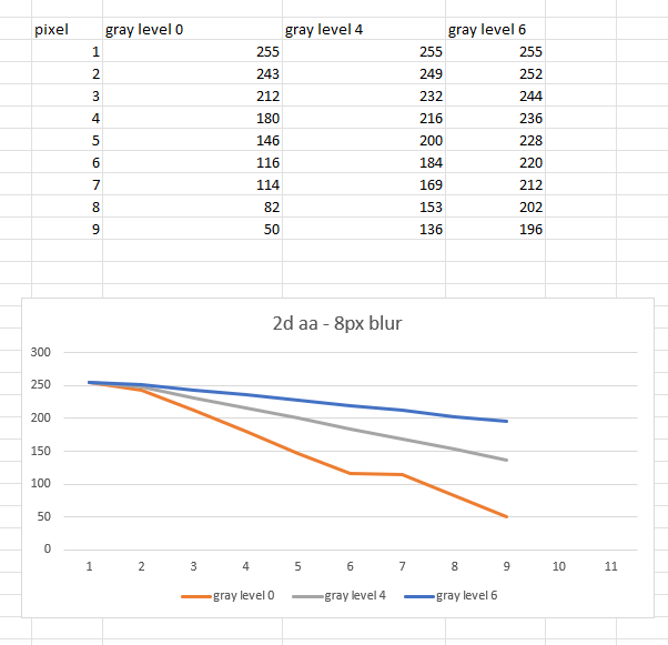
So if you use something like gray level 4 or 5 you already get a non-lineair effect in your shades of white. That should already result in better anti aliasing.

I do wonder why the anti aliasing comes after that process… seems it should be first anti aliasing, then this gray scale correction. The slice output seems to indicate so at least.

See image below. So using gray level 4, the exposure starts roughly at 128, instead of 0. Leaving only 128 values upwards. Using gray level 6 means it only uses 256/4=64 bits, so from roughly 192 upwards to 255.


#46

so with my system I can already get very smooth shallow angles, in fact it’s easier there, the main issue I have is trying to get layer lines to dissolve at higher angles. From 45-90 degrees assuming layer height and pixel size is the same, normal XY AA would be expected to do the job because all that is needed is some xy movement for such angles, or at least the steeper part of it like 60-90, but from say 30-60 it’s harder to get VAA to work because you need small partial layers but when trying to print that the result is just the edge of the layers moving because a gradient only 2-3 pixels wide is no different than XY blur/aa. That’s why I’ve been doing lots of testing with tiny gradients and stuff, but I think the biggest limitation I have here is just with my printer, I need a newer one with smaller pixels and a better light engine so less bloom.

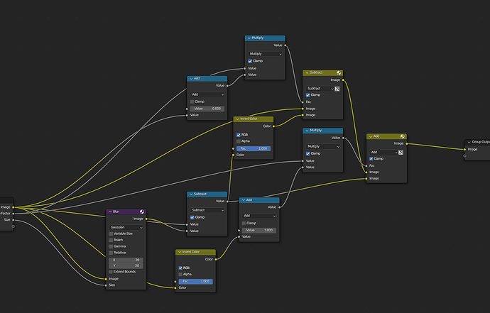
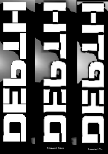
Speaking of which, just got some pics from a file I sliced from the same guy I posted a few things from already. Because of the overlapping layer technique things like text on surfaces get blurred at the bottom due to bloom so for these prints I used this technique I came up with which is meant just for gaps but it turns out it can help with this type of bloom too. Basically, it uses blur or dilate operations to simulate bloom expanding and closing small gaps, then it erodes the edges but small gaps that have closed won’t erode properly because the wall between them has been filled, this means we can now take away the original image and leave us with a map of all the spots where the gaps were filled by bloom, now we can dilate or blur this map and subtract it from the original image.


again this was just supposed to expand gaps to a distance where they will not close, 3 pixels is good for me and another person I’ve seen test gaps. I have a gap test here https://cults3d.com/en/3d-model/tool/ball-and-socket-joint-resin-gap-tester
but I need to expand it because j3d tried it and passed them all with one of his printers.

But yeha this technique ended up adding sharpness to interior corners like this

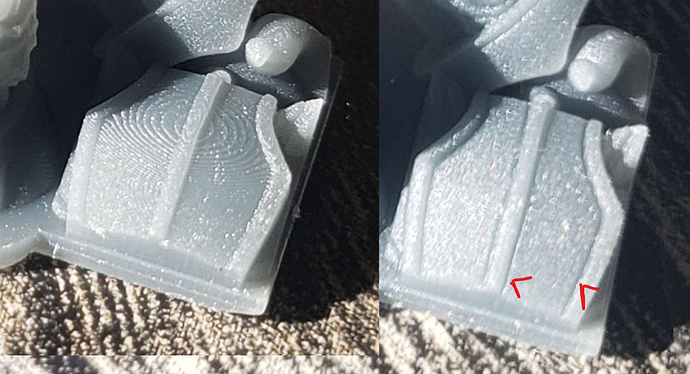
this was too much compensation but it can be adjusted, also I’m very happy with the vaa results here, it was done with a 34um anycubic by the guy who did the bases, he doesn’t have a great camera so it’s hard to see but it’s clearly better than what my printer can do.

No VAA:

VAA 0.5 curve strength, 5% high grey, 40% low grey 4 layers:

“My question to you about overlap was not how many layers, but how many pixels sideways?”

It’s not a number of pixels sideways that I do, I just read depth information for a multiple of the layer height so 4 L means at 50um layers I’m reading 200um of depth information below the camera to make the gradient, that way the gradient layers overlap. This is not the standard way to do VAA, only I have done it like this, everyone else like the ember team and you use 3d sub sampling to get accurate 3d AA that also works at very steep angles 45-90 as they show in their video with the 32 layer high tall thing where each layer gets a tiny bit wider until the bottom. While that’s very cool, normal AA blurs such angles anyway, it’s not accurate but it looks okay usually, I’m trying to make something that looks good as a priority so I just take vertical depth information from a camera in the scene to make gradients that do a great job at smoothing out the shallow angles where layer lines are most noticeable. Because you aren’t doing it this way the easiest way for you to overlap would be to just stretch out the gradient… I can do very high layer overlaps because while the layers are overlapping they are all sampling the geometry below so it’s still somewhat accurate, but if you just stretched your gradient out it wouldn’t, well it would be fine for a sphere but not anything with features so you won’t be able to stretch it out or even just expand the edge by a lot like me but you can try a few pixels, just enough to help reliably cover the shiny top of the last layer without having to use a high grey offset, speaking of which, with the linear gradient tests I’ve found using a lower grey offset 10-15% below the lowest on one the gradient works well.

If you want to do bigger and better layer overlapping you might want to try, before doing the grey offset stuff, take two layers and reduce the 100% value (fill area) of the lower one to 0 so you just have the gradient, then map it from 0-1 to 0-0.5 and map the higher layer from 0-1 to 0.5-1 and then add them together so you have a smooth 2 layer gradient and then apply the grey offset and that stuff.

“I do wonder why the anti aliasing comes after that process… seems it should be first anti aliasing, then this gray scale correction. The slice output seems to indicate so at least.”

idk much about chitu AA but in lychee they have a grey offset, and 0% is best because with XY AA values like 5% can work unlike VAA when it does nothing because for XY AA it’s just expanding the nearby voxel, while zaa needs to cure a new one


#47

Hi Tom,

So do I understand correclty that the width of your gradient is basically the ‘union’ of the difference in 4 layers?

So whatever the model ‘grows’ horizontally in the upcoming 4 layers, you make a gradient for that entire area in the current layer.

Then, that would mean you are printing smaller layer heights for say 3 layers and then the last layer would make the final piece.

example:
layerheight of print 50 micron
you want to get a detail of 10 micron,

layer1: 50 micron
layer2: 40 micron
layer3 40 micron
layer4: 30 micron
Total: 160 micron. => 50 + 50 + 50 + 10 --> so the last layer will only get 10.

This would assume that layer 3 the light reaches 60 micron deep
And that the last layer it would reach 70 micron deep

Did I get that correctly?
I’m trying to understand why it works.

kind regards
Elco


#48

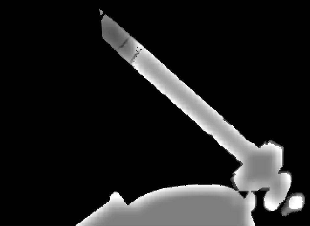
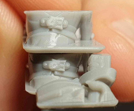
the layer overlap does make things taller, that’s why I also have started subtracting the gradient from the faces pointing down, that’s the compensation I was showing in a few examples like this image

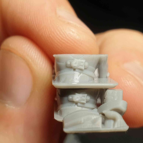
see how on the top one the belt buckle is thicker vertically compared to the bottom one, the bottom one uses the gradient from the layers pointing down to subtract a bit to compensate for the thickening from the layer overlapping on the top. This works surprisingly well but I haven’t tuned it to be accurate yet, just got it to look visually nice and sharp on models. I also offset the camera so that it starts a few layers up to adjust for the render being higher.

What you got from what I said sounds almost like another concept I have which I call semi continuous printing where (idk if I mentioned this already) you partically cure a few layers in the space of one without moving the z axis so you can have layer heights of say 20um but print times more like 100um, thats a different bag of worms though

is there another way I can contact you like discord so i can show you more directly?


#49

Hi Tom,

Can you send me an email at our info @ address? Would be happy discuss it more directly over phone/skype or something similar.
We don’t really use discord…

kind regards
Elco


#50

It has arguably the most advanced features of any non-industrial slicer, so increasing the slicing time to 20 is certainly acceptable, at least for us.


STEPPERMOTOR.F R has a wide range of motors, now available Stepper motor, Nema 23 stepper motor and so on.